Decoding a Relay with No Numbers
Several years ago, I wrote a series of detailed pieces on relays (you can find them here: part 1, 2, 3, and 4). I explained how a relay is nothing more than a remote-controlled switch that turns something on and off without having to have a large amount of current running into the passenger compartment. The common example is the little square headlight or fan relay that turns on the high beams or the A/C condenser fan by pulling the current through a thick wire connected directly to the battery instead of through the thin wires from the toggle switch that turns it on.
To summarize: All relays have a low-current side and a high-current side. The low-current side turns on and off a small electromagnet. The high-current side has the actual switch contacts. As I described in my original pieces, by far the most common type of relay is the single-pole-single-throw (SPST) relay with four terminals. One terminal of the electromagnet is fed 12 volts, the other is grounded. When current flows through the electromagnet, the magnetic field pulls the contacts in the switch together, connecting the two high-current terminals to each other.
There is a numerical shorthand applied to the terminals on a relay. It’s originally a German “DIN” standard notation, but it eventually was adopted by nearly all manufacturers. The DIN standard numbering for a common four-terminal SPST is:
High-current side (the device you want to turn on)
Terminal 30 | 12V from battery (fused)
Terminal 87 | 12V to device
Low-current side (the electromagnet)
Terminal 86 | 12V from switched power
Terminal 85 | Ground
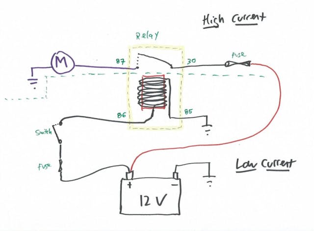
So, use beefy, high-gauge wires to connect terminal 30 to battery power and terminal 87 to the thing you want to turn on (the electric fan, the fog lights, whatever). Then use thin, low-gauge wires to connect the input of a toggle switch to power and the output to terminal 86. Connect terminal 85 to ground. Flip the toggle switch, and low current will flow through the electromagnet to ground, energizing it. That will pull the connections 30 and 87 together, causing high current to flow to your fan or fog lights. Neat, huh?
What I didn’t include in those articles years back was the neat method to figure out which terminal on the relay is which if the labels are illegible due to age.
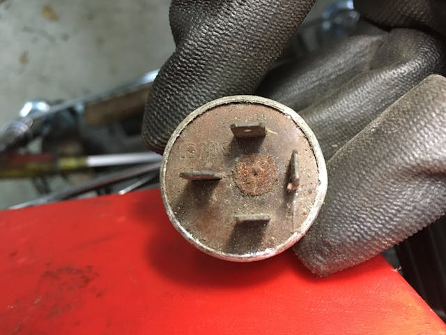
It’s very simple. Basically, you determine by trial-and-error which pair of terminals belong to the electromagnet. The other pair are therefore the terminals on the high-current side. Within the low and high-current sides, the terminals are actually interchangeable—that is, it really doesn’t matter if 86 is connected to 12V and 85 goes to ground or vice-versa, and the same is true for 30 and 87.
There are two ways to determine which terminals belong to the electromagnet. In both, you use the fact that if you mentally label the four terminals as 1, 2, 3, and 4, you’ll see that there are a total of six combinations to try (1-2, 1-3, 1-4, 2-3, 2-4, 3-4).
Way 1: Use a multimeter
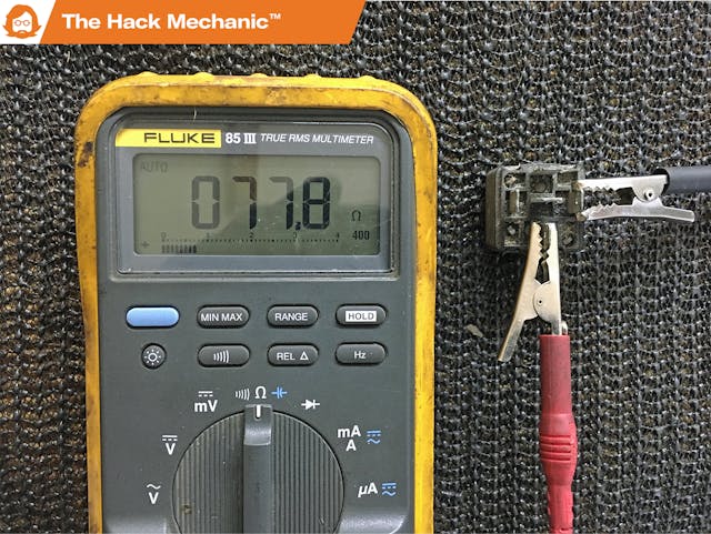
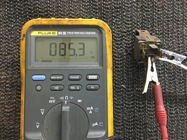
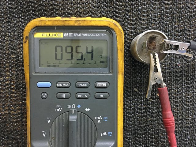
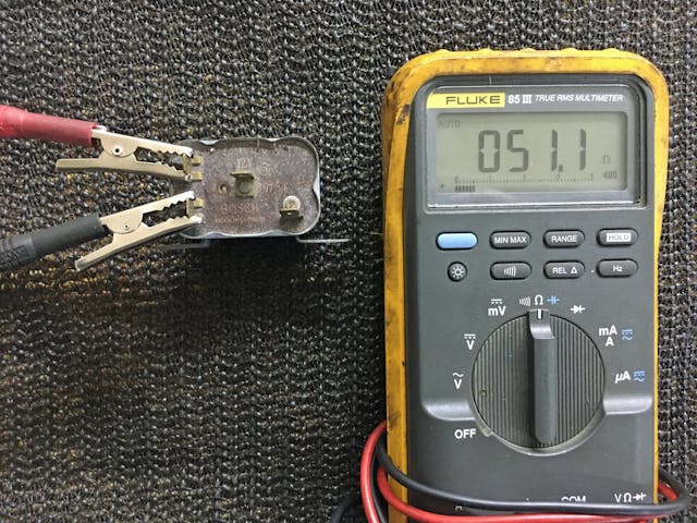
Take a multimeter, set it to measure resistance, and use the two probes to find the pair of terminals that have continuity between them. That is, if you’re measuring the resistance across anything other than 86 and 85, there should be no internal connection, so there will be zero continuity, so the multimeter will read “0L” for “over limit,” but when measuring across 86 and 85, it’ll measure the resistance of the windings of the electromagnet, which is usually in the 50-to-100-ohm range.
Once you’ve found 86 and 85, the other two terminals are 30 and 87. Note that if you happen to find a pair of terminals whose resistance is very low, like about one ohm, you’ve found the high-current pair, and they’re either stuck in the closed position, or the relay is a “normally closed” type instead of “normally open.”
Way 2: Hear the electromagnet click
If you don’t have a multimeter, take a pair of wires, each with a female quick-connect connector (commonly but mistakenly referred to as a “spade” connector) on one end and exposed wire at the other end. Connect them to any two of the relay’s terminals. Then touch the end of one wire to battery positive, the other to battery negative. It doesn’t matter which goes where, as either polarity will energize the electromagnet. Go through all six combinations. When you find the pair for 86 and 85, you’ll hear the contacts inside the relay click as the little electromagnet pulls them closed and click again when you release the wires.
Testing that you’ve gotten it right: Now that you’ve found the electromagnet contacts 86 and 85, and thus know that the two remaining ones are 30 and 87, you can actually test the relay as follows. You put a multimeter set to measure resistance across 30 and 87, verify that there’s no continuity (that it reads “0L” for “over limit”), touch the wires from 86 and 85 to battery positive and negative to pull the contacts together close the relay’s internal switch, and verify that the resistance between 30 and 87 has dropped to about one ohm.
Note that, as with 86 and 85, in practice, with a simple relay, it really doesn’t matter which one is 30 and which is 87, as it’s just a simple contact switch. If, however, the relay is in a modern computer-controlled fuel-injected car, it may have one or more diodes in it for noise suppression, in which case polarity is important. In this case, though, the relay is unlikely to be 50 years old, and the labels on it are likely to be readable.
The beauty of this technique is that even if the relay is a five-terminal single-pole double-throw relay that toggles between two devices, it still works. There’s still absolutely no internal connection between the low-current and high-current circuits, and there’s still only one internal electromagnet. Once you determine which pair of terminals is 86 and 85, the remaining terminals are for the high-current side, and by checking their resistance in pairs, you can determine which pair is normally open and which is normally closed.
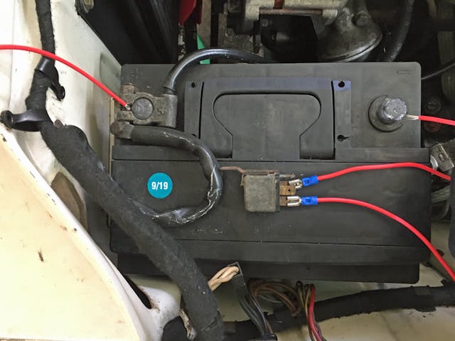
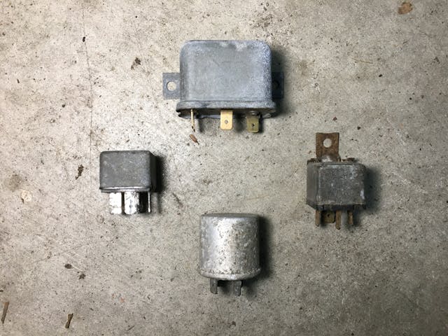
So, if, like me, you have a collection of old relays in a box in the garage and want to install one in your vintage car to turn on a set of new old stock Marchal driving lights—and still have the engine compartment look like it’s free of components purchased from Pep Boys—but you can’t read the numbers, in just a few minutes you can figure it out.
But don’t touch my stuff.
***
Check out the Hagerty Media homepage so you don’t miss a single story, or better yet, bookmark it. To get our best stories delivered right to your inbox, subscribe to our newsletters.


Rob; it’s likely that you are the most helpful Automotive-Fix-It-Writer around.
Hagerty should take a poll to try and see just how many you’ve assisted.
OK, fawning over.
Aw, thanks!
I’ll second that.
If you’ve never read his book “Memoirs of a Hack Mechanic”, I would strongly suggest picking up a copy. Seriously entertaining and full of helpful and useful knowledge at the end of each chapter. Should be required reading for all wanna be hacks.
Excellent article as always!
It’s also worth noting that a relay harness is an excellent upgrade for a lot of old cars. It took a long time for manufacturers to catch on that sending full current of the headlight circuit through the switch was a bad idea.
My w126 was upgraded by the previous owner with a full headlight relay harness and 100W hi/low beams (euro headlight conversion).
More recently, this past summer I wired one in to a friends Merkur XR4Ti. Anyone whose had one of these know the headlights notoriously suck. Even after the Sierra headlight upgrade. After wiring in the relay harness (just a generic Amazon special), he drove home in the dark. Later recieved a text with photo evidence that he was overjoyed with the results. Previously he avoided driving after sundown.
How did you wire the Merkur and what wattage bulbs did you use? I have an 85 and, as you said, the headlights are dim.
Be careful on the 86 and 85 terminals. Some relays have diodes across the coil, and then it does matter which is connected to B+ and ground.
I think I said that :^)
It’s a bit confusing? You stated it in the discussion on 30 and 87, which implied it mattered for that pair.
I was commenting on this statement near the beginning of the article, specifically: “…that is, it really doesn’t matter if 86 is connected to 12V and 85 goes to ground or vice-versa.”
I was working on a Mitsubishi Eclipse with no fuel pressure. This thing had these small package rectangular relays with no numbers. They all had four prongs. After a lot of googling, I could not find any resource that identified the pins.
I went after the problem from the other side of the circuit. No matter how you slice it, you are going to have two hots, one ground, and one path to ground with a load. Now your two hots may not always be hot. If you find one hot pin, you know it is the hot for the load. Chances are if you turn the key on or do some other act to energize the circuit, you will have two hots, and you should at this point know which is which. Now it is just about figuring out the ground. The one with the lowest resistance to a known ground is probably your best bet, but guess wrong and you are letting the smoke out of something. So put something in series with a known hot and your two ground candidates – like a light bulb. In one case, the light bulb should illuminate nice and bright. In the other, both things should try to work – for example, dim lightbulb and a fuel pump that is trying to pump up. Now if you run into a scenario where your mystery relay and socket come in the 4 and 5 pin variety, you automatically know the extra pin is the de-energized load path. If you are starting with just 5 pins, the above should work, but you will potentially have two loads that try to run, or one pin that just does nothing. Happy hunting at any rate
Look at you Rob, flexin’ with the Fluke multimeter! I’m slumming with the Hobo Freight they gave me for free.
As long as it has “ohm, ohm on the range”, it should be ok to use. Sorry, couldn’t help myself.
I need a fluke meter also. I have a freebee hobo freight one also.
Keep in mind either side of the relay can also be used as a switched ground. This is especially useful when adding a switch to the interior. No need to find and run wire to battery positive inside, and you can always find a place to ground the switch behind the dashboard or in the console area
He picked up some LED units from Amazon, but any bulb that is the correct style for the socket will do.
The relay harness is simple. It gives you a harness with two relays (low beam, high beam). One male plug, plugs in to the bulb socket (this triggers the relays). Then the harness gets strung to both bulbs and gets plugged in. Finally, you give it battery power and a chassis ground.
That’s it. If you hooked it all up correctly you’ll now have full battery voltage to your lights. Plus your unobtanium light switch stalk will last forever. (have you ever googled a replacement one for a Merk? HUNDREDS of dollars!)
I don’t correct you casually Rob but I’ve looked at it several times and I’m sure: you mislabeled the red high current line on your sketch as low current. Otherwise a concise article that solves a common real world issue!
The red line isn’t explicitly labeled as “low current.” There’s a dotted line diving the high current section at the top from the low current section at the bottom. The “low currrent” label applies to the bottom section. The red line has to be connected to the battery, which is on the bottom of the drawing. But, yes, you’re right that I wrote “low current” in a place that’s ambiguous.
Rod, here’s a third and more accurate way: it requires an old school test light with an incandescent filament type bulb. Test each pair of terminals with the test light connected in series to the battery and relay, and the other side of the relay connected to the battery. Then read the voltage across the relay when the test light illuminates. If it is zero or near zero, then you have found the normally closed contact and common contact. If it is approximately 0.7 +/- 0.1 volts, you have found a diode which is completing the circuit, and because the diode’s characteristic voltage drop is 0.7 volts, you know it’s a diode. Furthermore the battery terminal that the relay is connected to is the coil, and opposite in polarity to the battery, because the diode’s function is to shunt the reverse voltage spike when the power to the relay coil is shut off.
That’s a good trick. Thanks.