Understanding Relays, part 2: DIN numbers and different types of relay
Last week, we talked about the relay, and we did our best to keep it simple. That’s still the plan, although you’re about to learn a bit of German. (Don’t worry.)
First, let’s review. The relay is a remote-controlled switch that works on the principle that a tiny amount of current can be used to energize a little internal electromagnet. That electromagnet (a little coil of wire wrapped around an iron core) then pulls two internal switch contacts together that allow a much larger amount of current to flow.
The relay is best thought of as two separate circuits: A low-current control circuit that supplies power to the electromagnet, and a high-current load circuit that is enabled when the switch contacts are pulled together and allows a lot of current to flow to a load device.
Last week we offered a simple example using a relay that turns on an electric motor. It is reproduced below—this time with numbers on it.

DIN numbers and why they’re so helpful
What are those numbers? They’re called DIN-standard relay terminal numbers; DIN stands for Deutsches Institut für Normung (German Institute for Standards). Sometime around the middle of the last century, German cars began following DIN 72552, which is a numbering standard for automotive electrical terminals. DIN 72552 covers far more than just relays. It’s the reason nearly every ignition coil on a European car has the numbers “15” (power from ignition switch) and “1” (low voltage to distributor) on the two small terminals, and also why starter motors are labeled “15” and “30.” Perhaps it is most useful in describing, understanding, and troubleshooting relays since the function of a relay, the socket it sits in, and the wiring of that socket, can always be reduced to the DIN terminals.
Not all cars follow the DIN relay numbering standard—vintage British and American cars certainly don’t—but the standard was eventually adopted by virtually all automotive manufacturers. I doubt you’ll find a car built since the 1980s with a relay that doesn’t follow the DIN standard.
Here is the DIN standard numbering of the four terminals on every relay:
|
Terminal |
Which Circuit? |
Definition |
|
86 |
Low current (control) |
Relay coil + (power input) |
|
85 |
Low current (control) |
Relay coil – (ground) |
|
30 |
High current (load) |
From battery + |
|
87 |
High current (load) |
Output to device, normally open, pulled closed when coil is energized |
|
87a |
High current (load) |
Output to other device, normally closed, pulled open when coil is energized |
Why are five listed? Humor me for a moment; I’ll get to that in a moment.
We can now describe the relay circuit in the figure above using the DIN terminal numbers:
- When the external switch is thrown, terminal 86 receives 12 volts. Since terminal 85 is connected to ground, this causes current to flow through the coil in the electromagnet, which pulls the two internal switch contacts (30 and 87) together.
- Terminal 30 is connected to the battery. So when the electromagnet pulls the two internal switch contacts together, current flows from terminal 30 out terminal 87, which is connected to the device we want the relay to control, in our case an electric motor. Since the motor is grounded, this causes the motor to turn on.
Every DIN relay works this way. It energizes the electromagnet, which connects 30 to 87 and powers the device. That’s all it is. It simply connects 30 (power) to 87 (the device). Learn it. Live it.
Two main minds of relays
OK, that’s not quite all there is, but it’s close. The kind of relay I’ve described above, with the four DIN connections, is a Single Pole Single Throw (SPST) relay. This is overwhelmingly the most common kind of relay found in a car.
There’s also a less common kind called a Single Pole Double Pole (SPDT), or “changeover” relay. In it, the switch inside the relay has not just one position, but two—current can flow to one of two terminals at a time. When the electromagnet isn’t energized, terminal 87 is normally open as it is in an SPST relay, but a second terminal, 87a, is attached to the normally closed position of the internal switch. That’s the fifth row in the above table. When the relay is energized, 87 and 87a change places—87 is disconnected from 30, and 87a is connected to 30.
You can imagine a SPDT relay being used to switch between low beams and high beams (in fact, it’s a little more complicated than that, since there’s the flasher circuit, but conceptually it’s still a decent example). I found an SPDT relay in my 1972 BMW 2002tii in an unexpected place: the air conditioning. An SPDT relay is connected to both the heater blower box and a/c, allowing one of them to be on at a time, but not both.
Form factor of relays
Since the late 1970s, nearly all of the relays that follow the DIN standard have a very uniform look—they’re little 1-inch cubes. They’re often called DIN relays, or ice cube relays, or Bosch relays, as many of them were originally made by Bosch. While you can expect that any small square relay follows the DIN standard, my ’70s-era BMW 2002s have several weird-looking non-ice-cube relays that also follow the standard.
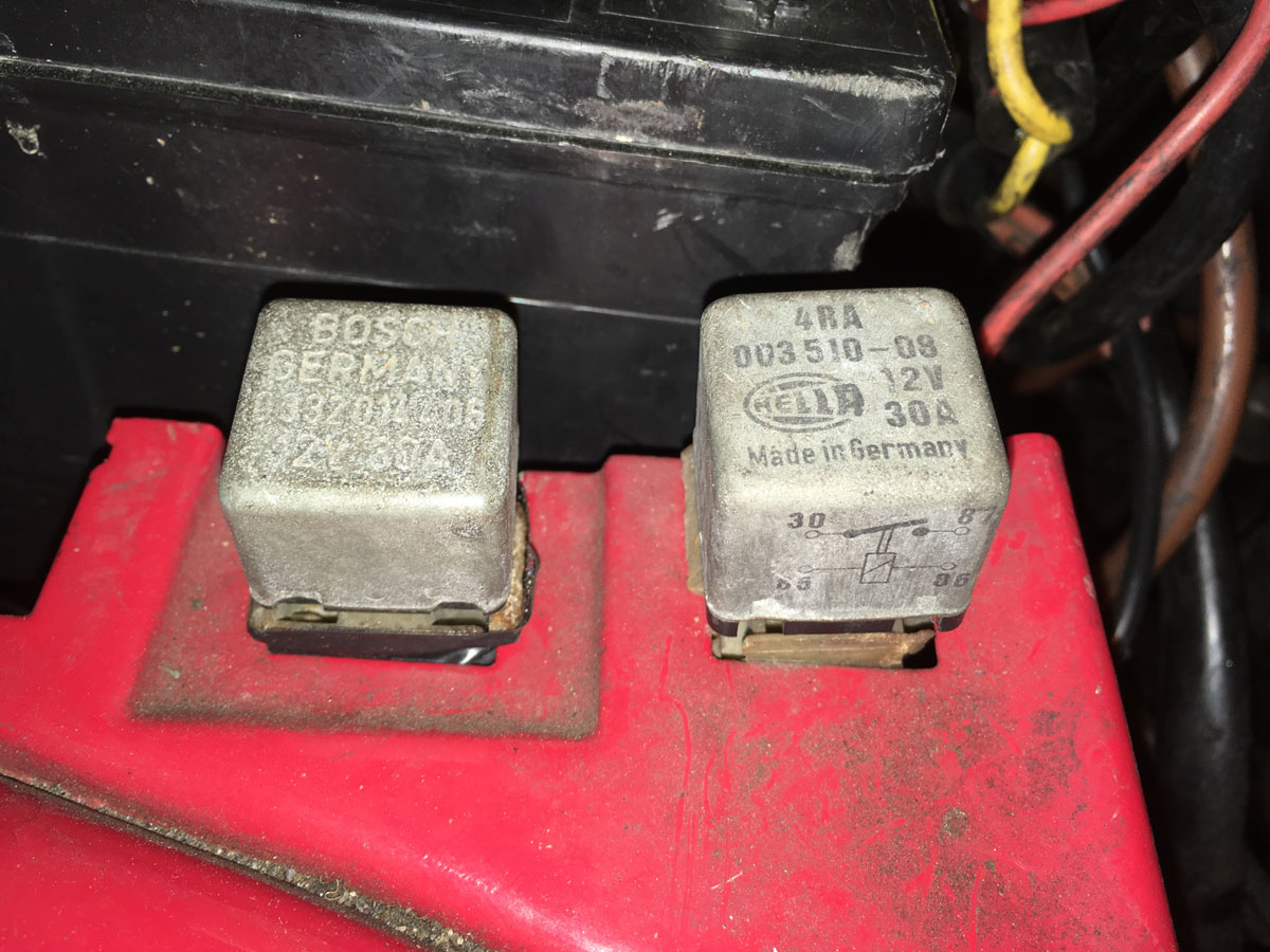
Let’s look at a square DIN relay and the socket it sits in. Below are two of the relays in my 1973 BMW 3.0CSi. Other than the new ones usually being in a plastic case instead of a metal one, they haven’t really changed. On the relay on the right, you can see the little schematic drawn on the side of it, which looks remarkably like my hand-drawn diagram showing the coil of the electromagnet with terminals 86 and 85, and the switch with terminals 30 and 87.
In the photo below, I’ve removed one of the relays from its socket and turned it over. All DIN relays should have the terminal numbers on the bottom. On mine, you can see the labels for terminal 87 at the top and 30 on the left. You can’t tell, but that’s 85 on the right, and 86 on the bottom. Sometimes the DIN numbers are also on the socket, but on this one they’re not.

Interchangeability of relays
Something you really need to be careful of is the difference between so-called “Type A” and “Type B” relays. Surprisingly, although the numbering of DIN relays is standardized, the terminal locations on DIN relays are not completely standardized. Terminals 87, 85, and, on a changeover relay, 87a, are I believe always in the same place, but terminals 30 and 86 can switch places with each other. For this reason, you need to be very careful rummaging through the spare parts box to find a relay if one of yours has died, or accepting one from a well-meaning passer-by. Note that there are only a handful of online references to “Type A” and “Type B” relays. Don’t call up a parts supplier and say, “I need a Type A DIN relay.” The take-away message is that you need to inspect and compare the pinouts of the old and new relays.

If you have the relay “type” nailed down, within both SPST and SPDT relays there are a few variations with internal diodes and/or resistors for noise suppression. The newer the car, the more variants you’re likely to find. Unless it’s an emergency, I don’t recommend replacing one of these with a generic DIN relay without the suppression hardware, as it’s there for a reason. You can swap them the other way, however—a relay with a resistor or a quenching diode can generally take the place of one without them.
Those few twists notwithstanding, to say it again, if you understand that powering terminal 86 and grounding terminal 85 energizes the coil, which then pulls the switch contacts together, connecting 30 (power) to 87 (the device), you know what you need to know.
Next week, we’ll talk about troubleshooting relays and relay circuitry, and the all-important trick of bypassing a relay by jumpering across socket terminals 30 and 87.
***
Rob Siegel has been writing the column The Hack Mechanic™ for BMW CCA Roundel Magazine for 30 years. His new book, Ran When Parked: How I Road-Tripped a Decade-Dead BMW 2002tii a Thousand Miles Back Home, and How You Can, Too, is available here on Amazon. In addition, he is the author of Memoirs of a Hack Mechanic and The Hack Mechanic™ Guide to European Automotive Electrical Systems. Both are available from Bentley Publishers and Amazon. Or you can order personally inscribed copies through Rob’s website: www.robsiegel.com.


Good article, and only item I would note is a typo under Two main kinds of Relays. The second and less common Single Pole Double Pole (SPDT) should be described as a Single Pole Double Throw (SPDT) device.
Good insight about relays . This has thought a great lesson.
Keep it up, Dude.