Understanding Relays, part 1: Why We Need Them and How They Work
A funny thing happened after my last story about troubleshooting a no-crank condition. I experienced a no-crank condition.
“Fortunately, the root cause of a no-crank is almost always simple,” I wrote. “Most of the time it’s simply due to a low or dead battery, or voltage drop through a corroded connection. Rule those out before you suspect the starter itself. But it could be the starter.”
Well, last weekend I jumped into my 1973 BMW 3.0CSi, a well-sorted and consistently driven car I’ve owned for over 30 years. I turned the key and… CLICK.
I tested the battery. It was fine. I cleaned the battery terminal connections. No difference. I swapped the battery anyway with another fully-charged one. No change (not that I expected one). I removed the starter’s power and ground connections, cleaned them with a file, reinstalled, and re-tested. Nothing.
Then I set up the multimeter to do a voltage drop measurement and turned the key. Again the starter went CLICK, but then half a second later the engine turned over. The timing of the two events was probably coincidental, however. I drove the car to buy ice cream, but these problems tend to get worse, not better. If you keep driving a car with mystery issues like this, odds are it won’t be long before you’re left stranded. That happened to me once when I drove my 1982 911SC to a funeral, but that’s another story. This time, I likely have a starter or solenoid that’s going intermittent.
In my last story, I also wrote that the solenoid “is essentially a remote-controlled switch—a special type of electrical relay—that allows the key to be turned and the starter motor to be cranked without having the hundreds of amps of current it draws flowing through the ignition switch.” That’s a great jumping-off point for this week’s topic: Electrical relays, which is also the first step to understanding how a solenoid works.
Here’s the deal. Certain electrical devices, especially electric motors, heaters, and headlights, draw a lot of current. By far the biggest of these is the starter motor. While the starter is cranking, it can draw hundreds of amps. That’s why there’s a fat battery cable going from the positive battery post directly to the starter motor.
So how, exactly, is the starter motor turned on? There must be a switch involved, right? And it must involve the key being turned in the ignition slot, correct? And that fat battery cable doesn’t really run up the steering column, does it? No, it doesn’t. Instead, it throws a switch by what is essentially remote control.
So how do you make a “remote-controlled switch?” As a thought exercise—humor me for a moment—imagine the first ones were made using rope. Imagine one of those big knife switches like the one you see Dr. Frankenstein use when he tries to energize his monster—one that is attached to an electrical cable as thick as your wrist. Now imagine that you need to flip that switch from the next room. Do you move the switch into the next room and run that massive cable there and back, or do you do something clever, like hook up two ropes and a series of pulleys to the switch—one rope to pull the switch closed and another to open it?
If you can imagine this, you’ve just conceived of a remote-controlled switch. In this case, the ropes are providing mechanical remote control and not, I hope, energizing the undead.
In your mind, simply replace those ropes with an electromagnet and a spring. That is, put a spring on the big knife switch so it normally stays open (the spring forces the two switch contacts apart), and put an electromagnet under it so that when there’s current flowing through the electromagnet, it closes the switch by pulling the two contacts together). You’ve replaced the rope’s mechanical remote control with the electromagnet’s electrical remote control. Congratulations, you’ve just imagined a relay. It’s a little box containing a little electromagnet and a little pair of switch contacts. Energize the electromagnet, and it pulls the switch contacts together. That’s all it is. Well, almost all.
Let’s draw the basics of a relay. An electromagnet is nothing more than an iron core surrounded by a coil of wire, so it’s usually drawn something like we show in the figure below. When you apply 12V to one side of the coil and ground the other side, it energizes the electromagnet, which, in turn, pulls the internal switch contacts closed. The electromagnet inside a relay is very small, so it draws very little current. The internal switch contacts, on the other hand, are typically connected to something that draws far more current.
Now we have to complicate the explanation by talking about low and high current. It’s really useful to think of a relay as two separate circuits—one that draws very little current, and the other that draws a lot of current. The electromagnet is on the low-current side of the relay, and the internal switch contacts are on the high-current side of the relay. This is, after all, the entire purpose of the relay—using low current to remotely throw a switch that then allows high current to flow. We label the low-current and high-current sides of the relay in the figure below.

To make it a little clearer, I’ll redraw the picture to show the case when the electromagnet isn’t energized and the internal switch contacts are open, and the case when 12V are applied to the electromagnet, which then pulls the internal switch contacts closed and allows current to flow through them.
, and energized so they’re closed (right).")
With this basic knowledge of how a relay works, we now can place the relay in the context of a circuit, where it does something useful—which is to remotely turn on a device. Let’s say it’s an electric motor. We’ve established that, when the coil is unpowered, the relay’s internal switch contacts are open and no current flows, and that when 12V is applied one side of the coil and the other side is grounded, the electromagnet pulls the internal switch contacts in the relay closed, allowing current to flow on the high-current side of the relay.
So what turns the current to the electromagnet on and off? Well, this is a little embarrassing. It’s a switch.
“What?” you’re asking. “I thought you said a relay was a remote-controlled switch! And now you’re turning it on with… a switch?!” There’s a perfect explanation for this. What you’re doing is throwing a small external switch, through which flows very little current, so you can energize the electromagnet … so it can pull the internal switch contacts closed … so a lot of current can flow through them instead of your small switch. In this way, you can run thin wires to your small external switch and use it to turn on something that, if you switched it directly, would require really thick wires to carry the current.
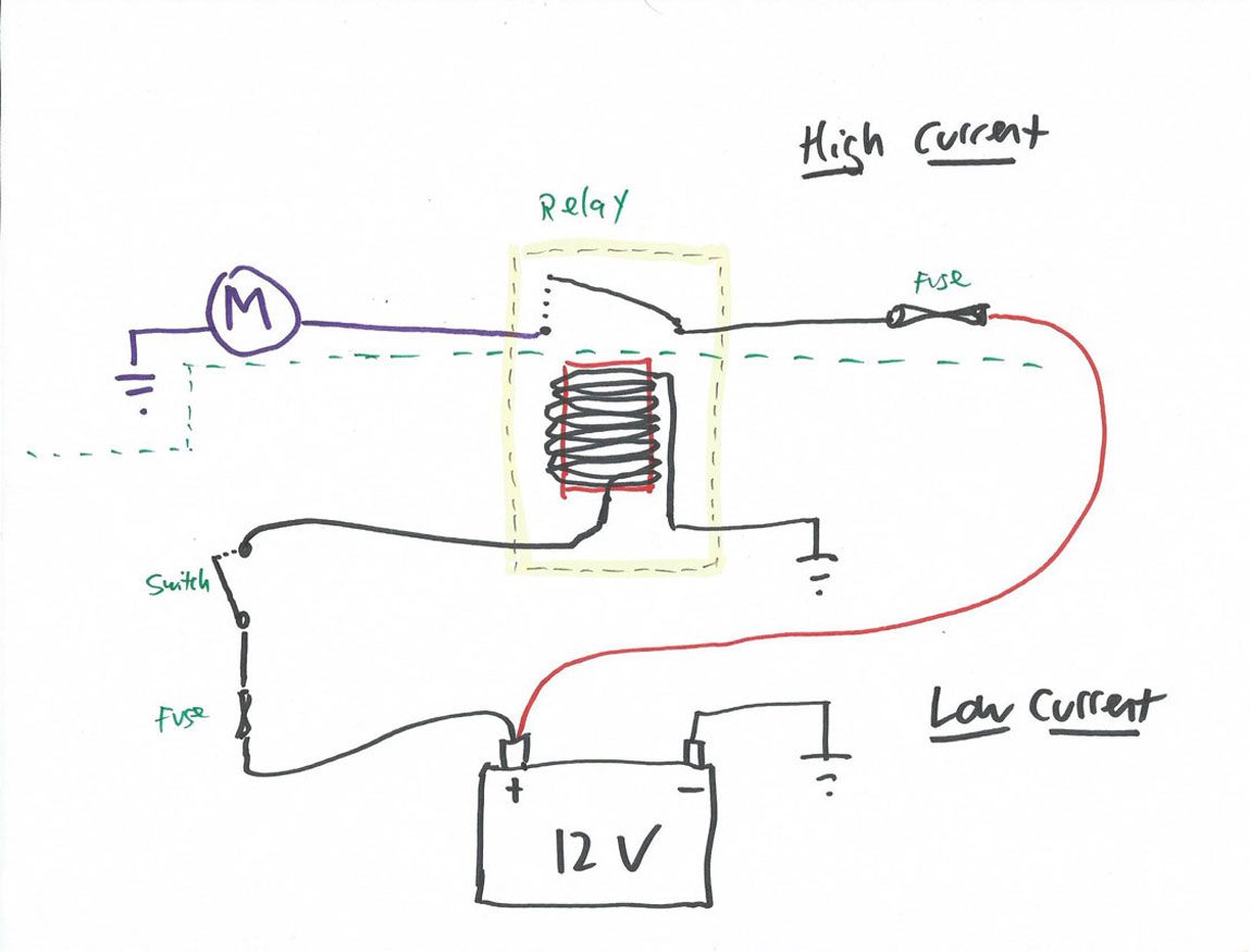
I lay it all out in the figure below. An external switch is connected to the positive terminal via a fuse. When the switch is closed, low current flows to the coil of the electromagnet in the relay, and then to ground. This energizes the electromagnet, which pulls its internal switch contacts closed. One side of the switch contacts is also connected to the positive battery terminal via a fuse. The other side is connected to an electric motor. So when the switch contacts are pulled closed, current flows through them to the motor, and from there to ground. This minimal example shows how the external switch and the relay conspire to allow you to turn on and off a high-current device without having the high current flow through the switch.
Next week, we’ll talk about the different kinds of relays, the standard relay DIN numbers, and how to jumper across a relay.
***
Rob Siegel has been writing the column The Hack Mechanic™ for BMW CCA Roundel Magazine for 30 years. His new book, Ran When Parked: How I Road-Tripped a Decade-Dead BMW 2002tii a Thousand Miles Back Home, and How You Can, Too, is available here on Amazon. In addition, he is the author of Memoirs of a Hack Mechanic and The Hack Mechanic™ Guide to European Automotive Electrical Systems. Both are available from Bentley Publishers and Amazon. Or you can order personally inscribed copies through Rob’s website: www.robsiegel.com.


Hi If I have extra devices connected to my battery that drain the battery very quickly. I only want them to start up when the car is turned on. Is a relay the correct option for that?
Not really, instead you should connect those extra devices to a power circuit controlled by the ignition switch, so when you take the key out it powers down.