Wrenchin’ Wednesday: Floor-jack cradle for lifting an 800-lb diesel engine
Today is a bit of a unique one, but as diesel engines grow in popularity as projects, learning to work around their incredible mass becomes something of a creative challenge. For my GMT400 Suburban with the 6.5-liter turbo diesel, the difference between the 454 cu-in big-block gas engine and the Detroit Diesel was over 100 pounds thanks to the diesel’s beefed-up block and turbocharging hardware, sitting around the 800-pound mark when fully dressed. When it came time to replace what were likely the original 1996 engine mounts, lifting the Detroit was going to take careful planning since the traditional wood-block-under-the-oil-pan trick would still collapse the pan under the engine’s own weight.
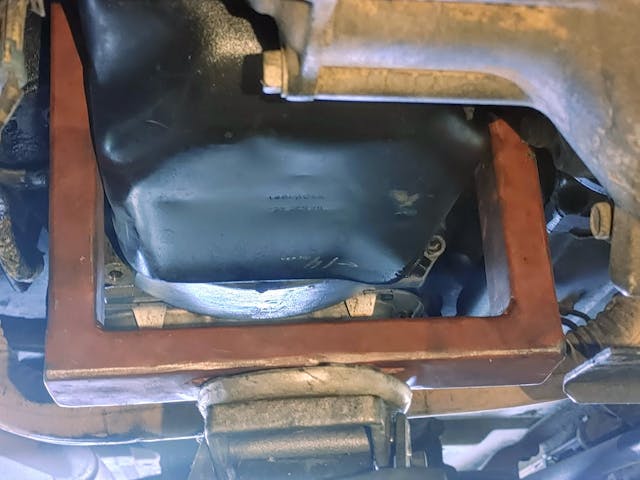
To get around this problem, rather literally, I designed a cradle for lifting at the block’s skirt. This would put the load squarely on the block’s main casting instead of a thin, stamped steel oil pan, which allowed me to lift the engine high enough to extract and replace the engine mounts. This isn’t a how-to, per se—everyone’s engine and car will require a different approach — but an explanation of the design process, since these support cradles can be made just as easily for transmissions, subframes, and other large-but-oddly-shaped parts.
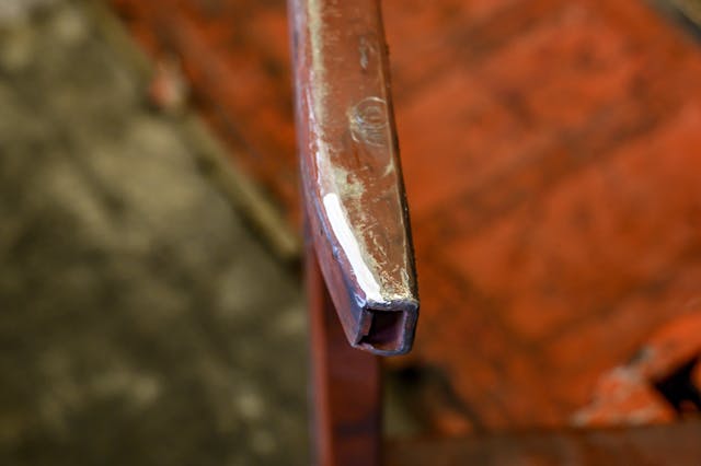
I selected one-inch square tubing, .120 wall. From tubing calculations, one bar had more than enough strength to support the weight horizontally, and I picked up a 20-foot stick at a local metal supply shop and hauled it home. The idea was to double-up the square tubing and stitch weld it. Overbuilding was the key, so the next question was: what did it need to look like?
Design it
The thought process when building a custom tool often stems from identifying what you can’t do bare-handed, why that’s the case, and how a custom tool can solve the issue. To support the engine, the tool needs to fit around the oil pan and situate itself on the block skirt (and fit between things like the starter and oil filter) and it needs to have a pad on which the floor jack can lift. Thinking like a candle that’s been lit from both ends now that the tool’s contact points are sorted, measurements helped me figure out the height of the cradle, along with its width. The contact patch for the cradle was also going to be limited by the placement of the aforementioned starter and filter.
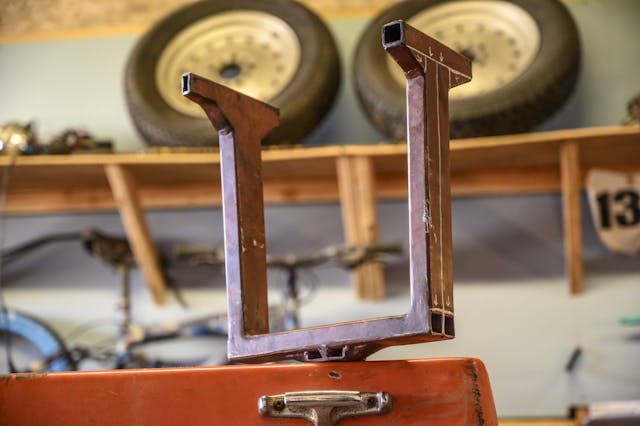
With rough measurements taken, the next move was to sketch out how each piece of square tubing stacked on top of the other, so that the weight of the engine was never going to hang by a weld, instead directing the load into the bar below it. I cut gussets to give the top of the cradle a little extra support, and because the floor jack has a cup (not a flat lifting point), I thought it wise to add a small contact patch with a few slices of square tubing. That way, the cradle rested in the flat center of the jack’s cup.

From there, it just became a game of hot gluing metal together with the MIG. I used a cold-saw to cut the 1 x 1 x .120 bar stock down into its core pieces, tacking each part together as I tested the fit each step of the way. This design-as-you-go process was the fastest way to work with the limited space between the oil pan and the surrounding parts under the engine, like trying different LEGO bricks until the right one fits. One of the contact pads even had to be narrowed to slip between the oil pan and starter, giving that pad some much-needed length instead of just chopping it shorter to avoid the tight spot entirely.
Build it
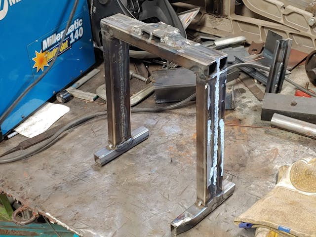
Once it was fitting tightly, the whole cradle had to be seam welded solid, with the rounded edges of the square tubing making for the perfect chamfer to fill with two passes of the MIG. I make no claims to be a professional welder, so I periodically ground them back for inspection.

Use it!
Once it was all welded up, I hit it with spray primer to seal it up from surface rust, and tossed it under the truck for a stress test—and when it began pulling weight off the tires with no deflection or stress, into service it went. This tool was built for when I was working from an apartment parking spot and didn’t have access to an engine hoist, backed-up by large wood blocks between the engine and frame in case the floor jack hydraulics failed. The primary goal was to lift the engine evenly and securely with the basic tools I had (other than an afternoon at a makerspace to weld), and with careful planning and material selection, this engine cradle achieved just that.

