Building adjustable links with heim joints
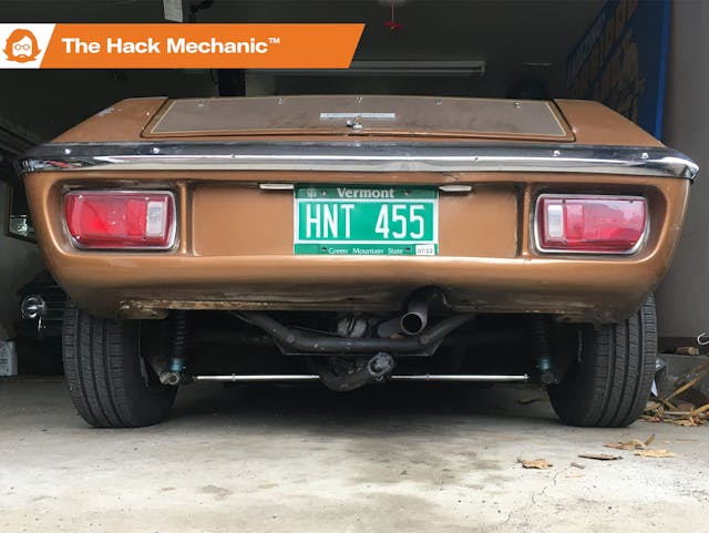
Several months ago, I wrote a piece about using a camber bubble gauge and a digital inclinometer to take some camber measurements on two of my cars. On my ’74 Lotus Europa Twin Cam Special—a car that has some odd handling characteristics during high-speed lane changes—I found that the front wheels were cambered inward at the top by more than a degree. This is a problem that I created by installing shorter springs to lower the nose of the car from its boat-on-plane federally mandated headlight height specification.
But of equal surprise was the fact that the rear camber was uneven. The Europa, due to its race-car heritage and designer Colin Chapman’s famous “simplify, then add lightness” philosophy, utilizes a “stressed member” design where there’s no rear subframe, and instead, the rear control arms are attached to the transaxle. Further, like most everything else on the car, the rear control arms are light little wispy things, reminiscent of hollow bones in birds’ wings.
In the Europa’s stock configuration, the front toe-in is adjustable via the standard method of threaded shafts on the tie rods. The rear toe is adjustable via a Byzantine arrangement involving spacers (washers, really) on the bolt connecting the rear trailing arm and the subframe. But there’s no built-in method of adjusting the front or rear camber. There are aftermarket suspension packages that offer such adjustability, but the commercially available adjustable front wishbones are expensive and appear to require the ball joint to be pressed out of its tapered hole each time an adjustment is made.
Fortunately, owing to the simple nature of the rear control arms, or “links” as they’re called on the Europa, it’s very easy to build adjustable ones. Hot rodders have been doing such things for generations.
Reading the Lotus forums, I learned that there are two schools of thought to this. One is that, if the rear camber is unequal side-to-side, something is likely bent or broken. And since the car has this “stressed member” design, it could be an engine mount. Find the problem and fix it rather than masking a problem. The other view is that any feather-light, 50-year-old car is going to have some history/settling issues, so after checking for damaged components, why not install the ability to adjust the rear camber?
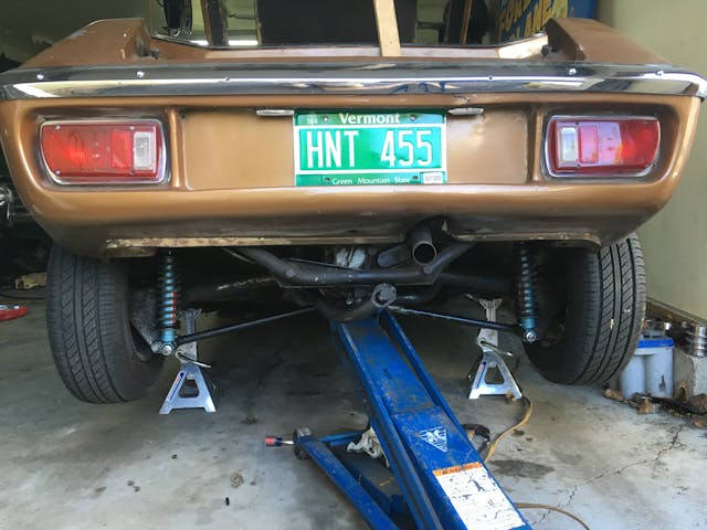
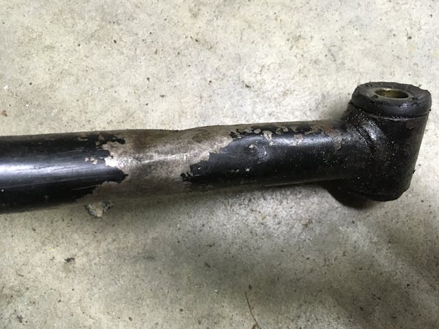
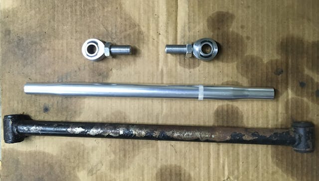
I put the car up on the lift to verify that I didn’t see anything egregiously wrong, and to my surprise, I did find that one of the tubular rear links appeared to have been dented, then straightened. The supplier from which I buy most of my Lotus parts doesn’t list the stock rear links on its website. Instead, it only lists in-house-built, adjustable ones for nearly $300 for the pair. They look as simple as they can be, with each one consisting of just a threaded tube and a pair of heim joints. I began thinking about building a set myself, and as these things often go, I couldn’t let go of the idea until it was done.
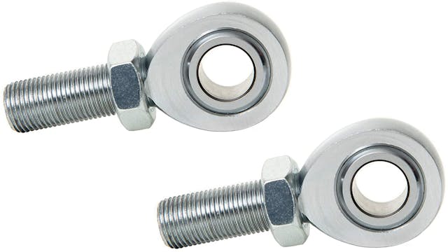
Adjustable links like these consist of three components:
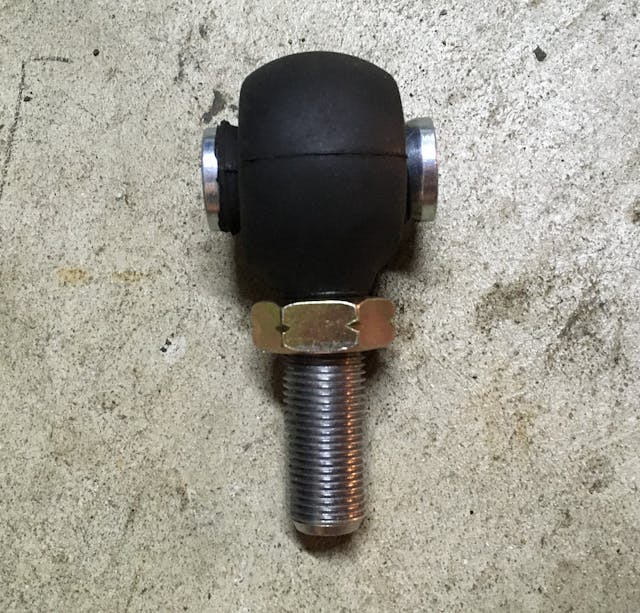
- At the ends are heim joints, which are eyelets with a threaded shank on the end and a swiveling ball in the middle, sort of like a metal marble with a hole in the center. They perform a function similar to the ball-in-socket configuration of a tie rod or a ball joint. Heim joints are specified by the diameter of the hole in the center and by the size and thread pitch of the shank. For either a steering application or a suspension component that will take a pounding, you probably want to steer clear (heh) of the low-cost two-piece joints and instead buy three-piece joints with a chrome-moly body, a hardened chrome-plated ball, and a Teflon liner.
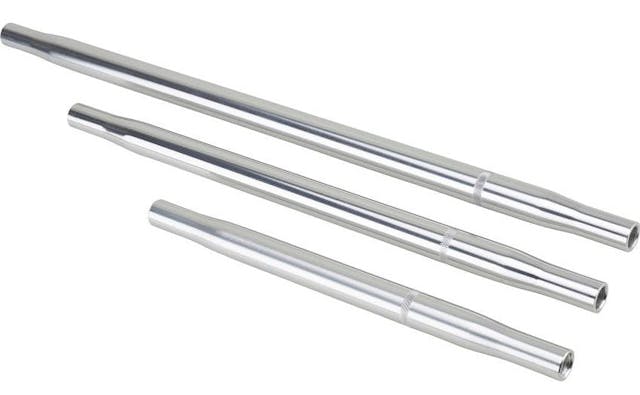
- The hollow tubes—referred to as “swedge,” “swedged,” or “swage” tubes—have a right-hand thread at one end and a left-hand thread at the other, making it so you can twist them and have the distance between the heim joints lengthen or contract.
- Lock nuts on the heim joints’ threaded shank seat against the ends of the swedged tubes and lock in the desired length.
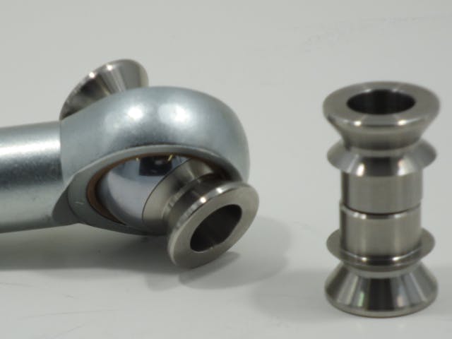
In addition to these three components, there is another often-misunderstood part—the spacers that provide standoff of the mounting hardware from the face of the pivoting ball. While you can have a washer or other flat surface directly contacting the face of the swiveling ball, you probably don’t want to, since the edge of the washer will hit the housing of the heim joint when the ball swivels. Instead, you want something with a cone shape that stands off from the ball and provides clearance so, as the ball swivels, the edge of the spacer won’t immediately hit the housing of the joint. For this reason, spacers for heim joint are often referred to as “cone spacers” or “misalignment spacers.”
However, if the geometry of the installation is such that the attachment points for the ends of the link are substantially offset from one another, causing the hole in the heim joint’s ball to rotate substantially away from the center, you may need “high-misalignment spacers.” These have a tall cone that allows the ball to swivel as much as 30 degrees before it contacts the sides of the joint. In order to provide structural rigidity for the tall conde, instead of the regular cone spacers that sit on the face of the ball, high-misalignment spacers have sleeves that slide inside the hole, are exactly the proper length and diameter, and come to rest on a little shoulder. This provides attachment that’s likely to be firm and free of play.
Because the sleeves slide into the holes, if you’re using high-misalignment spacers, you typically buy a heim joint one size larger than the bolt needed to attach them. For example, if the bolt for the needed component is 1/2-inch, you’d buy a heim joint with a 5/8-inch center hole, then buy misalignment spacers with a 5/8-inch sleeve and a 1/2-inch center hole. Lastly, if one or both ends of the heim joints are held in a bracket, then the height (often referred to as total mounting width) of the spacers becomes an issue, and it should be selected to match the bracket spacing as closely as possible in order to minimize the use of washers to fill the gaps.
Obviously, the diameter and threads on the ends of the swedged tubes need to match those of the heim joints and the lock nuts, and the size of the spacers need to match the swiveling centers of the heim joints.
So, with that, I set about to build myself a pair of adjustable links. The components are easy to find on racing sites like Speedway Motors, Jegs, and Summit Racing. The attachment bolts holding the original links were 1/2-inch, and there is some amount of offset between the ends, so I decided to use heim joints with 5/8-inch holes and employ 5/8 to 1/2-inch high-misalignment spacers. I noticed that the ones for sale from the Lotus parts vendor had 1/2-inch holes and no misalignment spacers or rubber dust boots. A rough estimate indicated that I could build upgraded version for about half the cost.
When ordering parts, the first thing you need to determine is the required length of the swedged tubes. If you’re replacing existing links like I was, you measure their length from bolt center to bolt center. That was about 18 1/2 inches. From that length, you need to subtract the amount that will be taken up by the body of the heim joints and the lock nuts. This requires looking at a drawing of the joints you’re thinking about buying. The sites I mentioned above may not have drawings on their site, but the ever-wonderful McMaster-Carr certainly does, and I found that for a 5/8-inch heim joint, typically the distance from the center hole to the top of the threaded shank is about an inch. There needs to be a lock nut on the shank, so estimate 1/4-inch for its height, and you see that each heim joint and its nut adds about 1 1/4 inches. Multiply that by two to account for the heim joints at each end and you get 2 1/2 inches. Subtracting that from the length of my existing links yielded 16 inches. Thus, if my calculations were correct, a 16-inch swedged tube with the heim joints screwed all the way against the lock nuts should be about the same length as my existing links.
Note, however, that this is the shortest that this adjustable assembly could be. That is, I could only adjust the heim joints outward from there and make it longer, which would increase the negative camber. It was likely that I needed to decrease it. If 15 1/2-inch swaged tubes were available, I would’ve bought them, but they weren’t, so I went with 16-inch, knowing that there was a possibility I’d need to shorten them.
I began ordering everything from Speedway, built around a set of 16-inch long, 1-inch-thick aluminum swedged rods with 5/8-18 threads, but they didn’t seem to have high-alignment spacers with the mounting width I needed, and I found what seemed to be better prices for a set of four high-quality three-piece Teflon-lined heim joints on Amazon. I found high-misalignment spacers with a total mounting width of 1 11/16-inch (close to the width of the bracket on the transaxle) and a set of well-priced rubber dust boots on eBay.
When the parts arrived, I began test assembly, and found that I couldn’t get two of the heim joints into the ends of the tubes. I eventually realized that none of the set of four had left-hand threads. When I looked at the item description in Amazon, I was surprised to find that nowhere did it say that the set included two right-hand and two left-hand-threaded joints—I had incorrectly assumed that from the language “set of four.” I returned the set and ordered two right-hand and left-hand ones, which weren’t as well-priced as the set of four. D’oh! I rolled my eyes at myself and my tendency to shoot myself in the foot while pinching pennies.
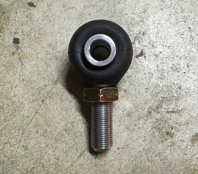
Finally, with everything on the garage floor, I assembled the pieces. Surprisingly, the most challenging step was getting the heim joints and the spacers inside their rubber dust boots, as the sleeves on the spacers wanted to pinch the rubber as they slid inside the holes in the ball. But once they were assembled, they looked like a nicely engineered set of parts.
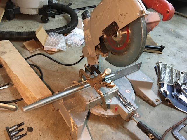
When I compared the assembled length to that of the original links, though, I found that, even with the heim joints screwed all the way in, the new adjustable links were slightly longer than the original ones, seemingly removing my ability to reduce the negative camber. I trimmed about a quarter of an inch off each end of the 16-inch swedged tubes. Since the ends of the tubes are the faces that the locknuts tighten against, I needed to make cuts that were square with the tubes. Fortunately, a good friend had a chop saw with an aluminum cutting blade that I was able to borrow.
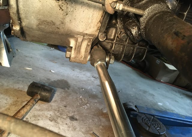
As it happened, though, once the new adjustable links were attached, it was clear that cutting them had been unnecessary, as I needed to rotate the swaged tubes to lengthen the links more than the 1/4-inch I’d cut off the ends. I don’t believe this was measurement error, but instead differences in exactly where things sat with the high-alignment spacers versus with the rubber bushings in the original links. Fortunately, there was more than enough length on the threaded shanks. If I had to do it again, I wouldn’t simply perform a length comparison with the old part before cutting—I’d actually install the new part in the car first.
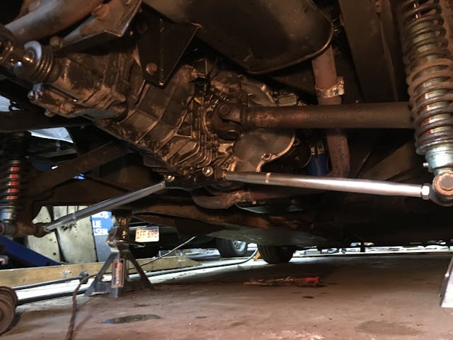
The mounting width of the high-alignment spacers was a good match for the transaxle bracket, requiring only one thin washer on either slide to take up the slack.
With everything installed, I lowered the car, moved it up and down the driveway to settle the suspension, and used the camber bubble gauge and digital inclinometer to dial the rear camber to about -0.5 degrees on each side.
In the end, I was a little over my goal of building the adjustable links for half what I could’ve bought them for, but as I said, mine included high-misalignment spacers and dust boots. Here’s the cost breakdown:
So, I now have adjustable rear links that enable me to dial in the rear camber. I still need to do something analogous on the front. However, that got back-burnered because, during the work under the back of the car, I discovered an unrelated but pressing issue with transaxle that required its removal, which I’ll cover next week.
But hey, not having a shortage of winter projects is a good thing, right?
***
Rob Siegel’s new book, The Best of the Hack MechanicTM: 35 years of hacks, kluges, and assorted automotive mayhem, is available on Amazon. His other seven books are available here, or you can order personally-inscribed copies through his website, www.robsiegel.com.


Rob. Do you still have the OEM rear stub axles installed? I believe they were sourced from the British Rootes Group Hillman Imp. I also understand they have a reputation for the end nut coming off and the wheel departing the car at high speed. I have read on various old blogs that a common ‘cure’ was to use the rear stub axles from the BMW 2002 as they were made from superior steel and much stronger than the Imp ones. I believe they are either a simple mechanical swap, or simple if installed with the BMW sized bearings or used with the whole BMW brake drum assembly. As your familiar with both product families I wondered if you’d looking into the change.
I ask as I’m in the early stages of installing a Nissan Leaf EV power-train in place of the original Renault R16 engine and trans-axle in my 1970 S2 Europa. The added torque from the Leaf motor makes me think it could snap 50 year old Imp axles too easily. The Leaf uses CV joints so I intend to change the stub axles for some with the flange to attach to outboard CV joints using a custom half shaft to suit each end. I believe that some later Beemers used the same dimension stub axle but flanged for CV joints. Can you confirm this?
Oops. “As your familiar with both product families I wondered if you’d looking into the change.”
Should read “As you’re familiar with both product families I wondered if you’d looked into the change.”
I have a 73 Europa, same as yours down to the color. Trying to duplicate this linkage change but have not been able to get the rubber boots over the helm joint. Ruined one rubber so far and don’t want to ruin more. How did you get the boot over the joint? Don’t spare any of the details.
Regularly read your columns and throughly enjoy them. Many of your lotus issues I have as well.
Thanks.
Bob
Michigan