Is this the next great leap for internal combustion?
We may have been doing this wrong all along. With cylinder heads, that is.
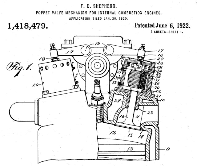
Back when it all began, steam was the start—how we first captured heat energy from fuel and put it to work. More than a century ago, steam powerplants formed the basis for the design of the first internal-combustion (IC) engines. Moving the combustion from an external source (a steam boiler) to the inside of the drive cylinder was a major step forward in power and efficiency.
Since steam engines were laying around all over the place, many parts were carried over. Components like pistons, connecting rods, and cranks were near-enough correct to make a gasoline engine sort of run, and things evolved from there. The sliding sleeves and popular barrel valves used to control the flow of high-pressure steam, however, did not make the cut. They leaked.
Leaking a little high-pressure steam here and there is not of major consequence in the grand scheme of a locomotive. Because cylinder leakage carries real drawbacks with an IC engine, sleeve valves and barrel valves were abandoned, replaced by a kind of valve called the poppet. The type of valve now found in almost every four-stroke IC engine on earth.
Poppet valves were and are a decent fit for a four-stroke’s high internal pressures and combustion temperatures. Mated with a countersunk seat, the poppet’s chamfered face forms a positive seal, and that seal improves as pressure on the valve face increases. Although they require complex drive and support systems (cams, keepers, springs, lubricated guides, etc.) poppets have been developed into a reliable solution.
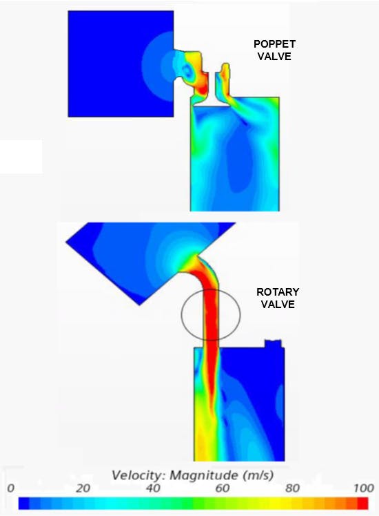
What we gained in reliable sealing, though, we lost in flow. A poppet valve’s head is always in the way. On the intake stroke, a poppet valve’s head blocks about 20 percent of the air trying to fill the cylinder. With the exhaust stroke, the valve is essentially attempting to evacuate a crowded theater through a door that won’t fully open. The piston is rising, pushing combustion byproducts out the exhaust port, but the valve’s head is in the way.
In the case of the intake valve, we’ve evolved to a sweet spot where a poppet can flow more than 100-percent capacity—more air can be moved past the valve and into the cylinder than the dimensions of the intake path and cylinder would suggest. But that’s due to the velocity of the incoming airstream, the air “ramming” itself past the valve’s head. (For an exaggerated illustration of this effect, see the now-outdated Japanese “subway stuffers”—they were literally ram effect personified.
This is no small issue. Every engine is, in essence, a dumb air pump, limited in its ability to bring in air. Burning gasoline and exhausting high-pressure gases are pretty easy tasks by comparison.
Cylinder filling has been the problem for two centuries, since we began moving away from steam. The column of air sitting over the earth weighs only enough to create around 14.5 psi of ambient pressure at sea level. When it comes to pushing air into a vacuum—like the one created by a piston moving down a cylinder—that pressure isn’t much. It’s even less at altitude, like on Pikes Peak, where the mountain’s height leaves the air column above short enough to give less than 9 psi. (Ever wondered why turbo- and superchargers predominate on race cars run at altitude? Now you know.)
After 100 years of being fussed with, the poppet valve is, in a sense, grandfathered in. It is now highly functional but not optimal. We have band-aided the poppet’s poor performance partly by increasing the number of valves—some cylinder heads have four or more per piston. Over the last century, however, the inventive human mind has tried to revive certain steam-engine concepts, to take advantage of their superior flow ability.
During World War II, when air power was the ultimate arms race, engine designers on both sides dusted off the concept of sleeve valves. By configuring those valves around pistons, they found tremendous power improvements. (While also making massive progress in the development of things like high-octane fuels, superchargers, turbochargers, and nitrous-oxide injection—all over the span of about five summers.) The power increases came mostly from the airflow made possible by those sleeve valves, a clean and unobstructed path from intake port to cylinder, no poppet head in the way.
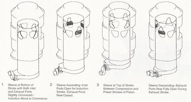
This improved air flow was put to good use: A fighter plane that can out-climb or outrun an opponent can easily turn and shoot them down. For all the benefits brought by their improved flow, though, sleeve valves leaked oil, they wore out too quickly, and they required monkey-motion levers in the crankcase in order to work correctly. The technology never made it to automotive production in any significant form.
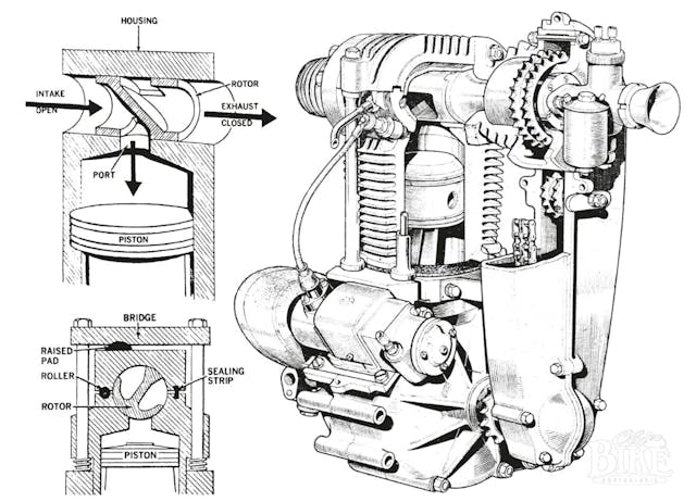
Still, the siren song of full flow capacity is hard to resist. And like the sleeve valve, the barrel valve—a type of rotary valve—has long captured the fascination of engine designers.
A shaft with a slot cut into it, rotating in seals, is so simple and capable that it has been tried dozens and dozens of times. Where a standard poppet valve may peak at flowing 85 percent of its intake area (and then only temporarily, when fully open), a rotary valve opens faster and can flow 100 percent of its intake area more of the time (meaning, over more of the valve’s opening duration). If you have a 5.0-liter engine that can only breathe at 85 percent of capacity, you don’t really have a 5.0-liter engine. One-hundred-percent intake-valve flow makes more power every time.
With the barrel valve, the gremlin has always been sealing. For a long time, any seal material that pressed against a barrel valve’s shaft enough to contain combustion pressure—upwards of 1500 psi at 2500 degrees Fahrenheit—would also give high friction and wear. If you loosened up the seal’s tolerance on the shaft to reduce that friction, it would leak. Either way, the high temperatures ate away at any sealing material tried.
The industry birthed prototypes, test engines, and a few production attempts, but no rotary-valve design or layout has been fit for real commercial success. Felix Wankel, the inventor of the rotary engine, started his career developing disc rotary valves that were eventually used in German torpedoes. In 2004, the Mercedes-Ilmor Formula 1 team got as close to the summit as anyone, with an adaptation of a rotary valve patented by a man named Bishop. But alas, F1’s (power-hating?) sanctioning body responded by outlawing any valve not a poppet. So much for racing promoting innovation.
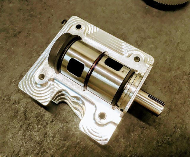
All hope is not lost. As part of my work as a professor of IC Engine Design at UNC-Charlotte, I was called to consult in “Race City, USA” (a.k.a. Mooresville, North Carolina, home of NASCAR), to assist a company that had found a way to seal a rotary valve and take advantage of the potential.
That company, Vaztec, was founded by a team of engine developers who had supported GM and Ford racing for decades, and who had grown disillusioned with how badly a poppet valve actually flows. Now six years in, they have just returned from a Society of Automotive Engineers conference in Japan, where their white-paper presentation on a successful rotary-valve design won an award.
Maybe time is nigh for a change.
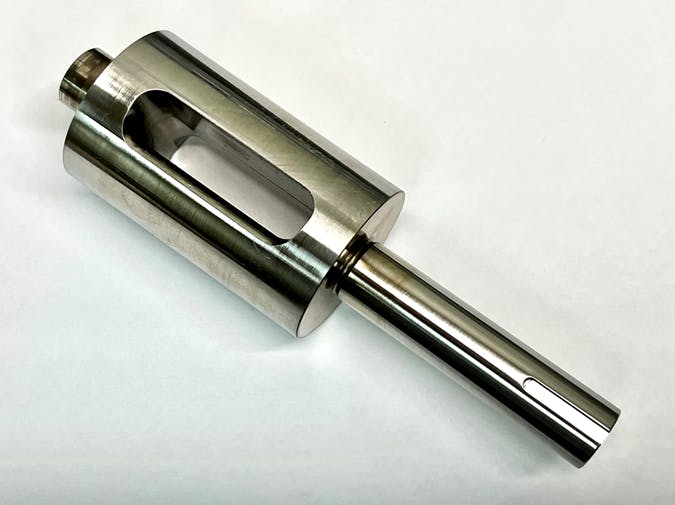
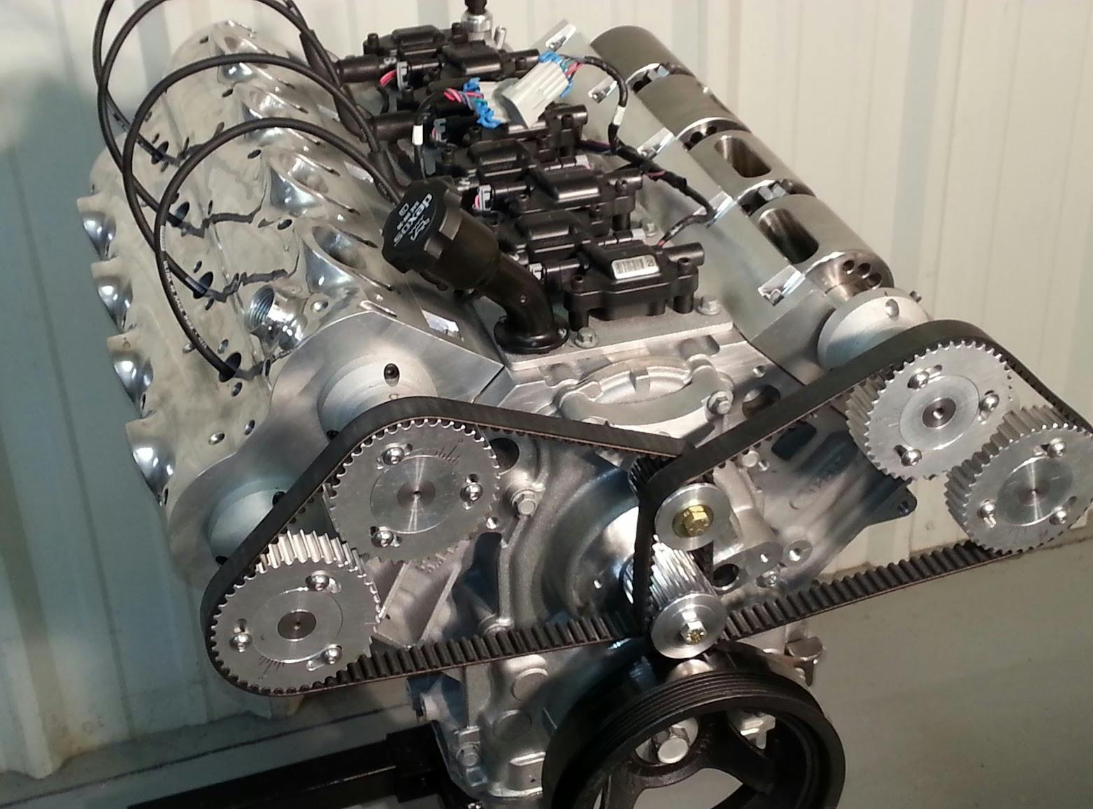
Vaztec has developed and patented a dynamic, high-temperature sealing system that adapts to the shape of a rotary valve as it expands. That expansion is the true Achilles heel of a rotary-valve system. Almost all metals expand as they heat up. If your valve seal relies on a thousandth of an inch of clearance to work, as many automotive seals do, having that valve grow three times that amount as the engine warms is a recipe for failure.
As the Vaztec project advances, some interesting side benefits have appeared. One is a cooler-running valve. The poppet is a sitting duck in the combustion chamber, exposed to 2500-degree combustion gases during the piston’s power stroke. Then, during the exhaust stroke, the valve’s head gets stuck in a jet blast of 1400-degree exhaust. Milliseconds later, that head carries leftover heat into the engine’s next power cycle. Because a barrel valve is constantly turning, heat transfers more evenly into the cylinder head.
That heat transfer is helpful. At peak power, the head of a poppet exhaust valve can serve as a “glow plug,” growing so hot as to spontaneously ignite fuel and air. Lowering an engine’s static compression ratio helps alleviate this; by the same token, if you eliminate the glow-plug effect, you can make that ratio higher. All else being equal, higher compression ratios improve power and efficiency—a strong step toward keeping the IC engine alive and relevant in years to come.
Those benefits were somewhat expected. An unexpected byproduct of unobstructed intake flow was the increased, and now very high, velocity of intake air as it rushes into the combustion chamber.
Intake air gets up to crazy speed in high-load conditions—Mach 0.55, or around 450 mph. That velocity is what drives the aforementioned “ram effect,” the jamming of a combustible air-fuel mixture into a cylinder. That velocity generally produces turbulence, which stirs up and quickens the combustion process, aiding power.

Interesting side note: A few decades ago, I had a fascinating conversation about intake velocity with former Car and Driver editor Gordon Jennings. He proposed Mach 0.9 as the actual goal—near-sonic airflow. Even then, however, things would still be greatly disturbed by the poppet valve’s head, which hangs out at the end of the intake port like a bouncer at the entrance to a party. With the bouncer gone, things change. Rather than an orderly “deflagration” (picture of a sheet of paper lit by a match at one corner, the flame moving slowly to engulf the page), we get flame-folding and combustion that takes place much more quickly.
This is a different type of cylinder process than we are used to, one highly efficient, very rapid, and very useful. A telltale is how Vaztec’s development engines have required roughly half as much ignition-timing advance as they would with poppet valves. Because the fuel-air mixture burns quicker, these engines can fire their spark plugs later in the compression stroke, which lets them make more power—the force of the cylinder’s burn is no longer trying to shove the rising piston back down. (With slower combustion rates, this is a very real “taxation” cost of advanced ignition timing.) The greater turbulence also sweeps lazy end-gases into the combustion party, giving less time for detonation sites to emerge in the chamber.
Designing a new engine system is one thing. Actually getting it to run is another. Six years ago, Vaztec began developing its rotary valve inside, of all things, a diesel engine. Diesels use extremely high combustion pressures, up to 2500 psi, so this was a tall bar, but also a fine way to prove the idea. Next, the company set its sights on the power kings of the engine world: two-strokes.
A two-stroke cylinder has a firing cycle every crankshaft rotation. A four-stroke fires only every second rotation, half as many power pulses for a given rpm. Although two-strokes excel in power output per cubic inch, they offer relatively poor control of incoming and outgoing gases, and that serves as an upper limit for output. (My ’72 Bultaco 250-cc two-stroke motocross bike made 144 hp per liter when I raced it 45 years ago, and Honda’s two-stroke, 500-cc NSR 500 grand-prix bike made 400 hp per liter in the 1990s. Compare these to the laudable 5.5-liter V-8 in the current Corvette Z06, which makes 122 hp per liter. What two-strokes don’t do well is run cleanly, which is why federal emissions regulators are eyeing them for eventual banishment.)

As a test, Vaztec set its sights on making a high-power, clean-emissions replacement for a 50-cc two-stroke, in the form of a rotary-valve four-stroke. This was the topic of the award-winning SAE presentation mentioned earlier. Vaztec’s rotary-valve, 45-cc single matches the power of a production 45-cc two-stroke chainsaw/weed-trimmer engine, and it can rev just as high (more than 12,000 rpm). It also made 50 percent more power than a similar, 48-cc four-stroke poppet engine currently on the market.

About that rpm peak: Poppet valves give an engine an upper speed limit by nature. At extremely high rpm, a spring-closed poppet valve will float—hover off its seat, unable to fully close and seal before the cam that controls the valve forces it open again. Since a rotary valve spins like a shaft, supported by bearings (imagine a camshaft without lobes or loads), it lacks that traditional limit. That Mercedes-Ilmor F1 engine easily spun above 20,000 rpm, limited primarily by the strength of its crankshaft and connecting rods.
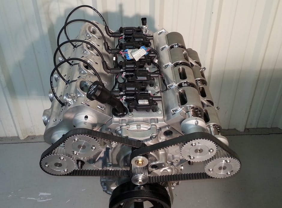
For a more automotive-scale test, Vaztec has developed a one-cylinder engine with two rotary valves, one each for intake and exhaust. This engine uses a 90-mm bore and a 70-mm stroke, which makes it comparable in size to one cylinder of a 1.8-liter in-line four. It currently makes 50 percent more power at 4000 rpm than the similarly sized poppet-valve engine that Vaztec chose as a baseline. Very promising.
On the endurance front, Vaztec has built ten prototype engines over the past six years, from a 28-cc single to a 5.3-liter version of GM’s LS1 V-8. The company’s engineers have hundreds of hours of durability tests showing scalability and strong results. The valve itself is simple, with very little to deteriorate. Even at these early stages of development, wear rates of these prototypes extrapolate to an engine life exceeding 5000 hours.
At the moment, Vaztec is working with engine manufacturers to scale the technology into powersports, and eventually automotive-production applications, including hybrids. The greater power density, improved combustion, and increased efficiency are coupled with reduced noise, reduced vibration, and reduced wear. On top of that, those benefits are brought by a system that uses 33 percent fewer parts than a traditional poppet arrangement, that requires no special materials or processes to create, and that costs less to make and assemble.
An added bonus? No valve adjustments for the life of the engine. And we get to keep our pistons and crankshafts.
While most of the advances in engines in the past three decades have related to controls like direct fuel-injection and variable valve timing, it seems we’ve found a way to improve the fundamentals once more.
Could the poppet valve go the way of the choke lever and dashboard cassette player, into the dustbin of history? Perhaps, just as carburetors have been largely replaced by fuel injection, rotary valves will take over. We shall see.
***
Full Disclosure: Norman Garrett is an engineering consultant for Vaztec and has helped develop the company’s rotary-valve technology. He is a freelance contributor to Hagerty and was paid for this story.
Check out the Hagerty Media homepage so you don’t miss a single story, or better yet, bookmark it.
Great article, but no mention of exactly how Vaztec overcame the sealing issues!
A wonderfully informative and thought provoking article!
Would altering the size of the rotor openings act as a if the engine had a camshaft change, a change in valve size, or both?
I vaguely recall reading about a rotor-valve engine with the valve being a disc and the opening rotated into position when flow was required. I think Ford was involved on some level at some point.
Very interesting. I would love to see this make it’s way to production.
Too late….TESLA…range is enough and getting better….ICE is nice, but it will be for luxury and play…..If you have ever been in the RC car world, you will understand.
Electric cars have three problems:
Cost, range, charge time.
None of these problems have been solved in any meaningful way. And even if you can share your car from 20-80% in 20 minutes, that’s not really good for the battery and you need a very powerful charger. A Toyota Camry will go about 600 miles on a tank of gas and refuel anywhere in 5 minutes. And electric car costs an extra $20k, goes half as far, and only partially recharged in half an hour. EV’s have a ways to go.
Well I don’t know about you but I cannot drive the 8 plus hours to utilize that 600 mile range of the mentioned Camry. My old body needs to stretch out and my bladder is just too small. We have made several 2400 mile road trips the last few months and find that stopping at about 300 miles is best for us. My nephew and niece tagged along one trip in their Tesla. I was surprised at the numbers of gas stations and rest areas that had installed high capacity chargers. Sure, it only takes about 5 – 10 minutes to pump our gas but by the time we make our requisite pit stops and grab a snack or coffee we have used up about 20 – 30 minutes. At a couple of fuel stops they were ready to go before we were.
As for in town driving, that 600 mile range means nothing, The Tesla can be fully charged every evening while sitting quietly in the garage, I have to stop at a gas station to fill up at the cost of a half hour of my time which could be better spent reading these articles.
So for my money, the only downside to an EV is the increased vehicle cost.
You forgot that you don’t have a fast charger at home. If you have a long commute in the winter where your battery is reduced by 20% or so. You don’t start off with a full charge each day. Then as you use more charge each day than can be recharged you end with a net loss of charge for the day until you get to the point that the car won’t have enough charge for the commute, so you need to leave the car to charge for 2 days to get that full charge you need.
Do you have any idea how electricity is produced?? The majority is produced by burning fossil fuel. And will continue so until a better method is viable. Most likely fusion.
Electricity is made by burning fossil fuel to heat water to steam. Then the pressure of the steam spins a turbine, then it turns a generator to make electricity. The electricity is passed through the power grid to a distribution point somewhere within 20 miles of the point of use. Then it gets transformed down to voltage that can be distributed to neighborhoods. Then near the point of use it gets transformed down again to a voltage that the user can use. At your home the power gets converted to DC to be able to charge the batteries. The batteries convert this DC power to chemical energy to store it for later use. Then when you drive the car it converts the chemical energy back to electrical energy. Then the electrical energy gets modulated to be able to control the motors to give you the power and speed desired.
All along each of these steps there is energy losses and ultimately the EV burns more fossil fuel than the ICE vehicle which creates more carbon emissions.
The automotive manufacturers gloss over these facts because the cost of manufacturing an EV is greatly reduced over an ICE vehicle, which helps their bottom line.
These automotive manufacturers lobby government to move to EVs because they have no tail pipe emissions and are better for everyone.
I never get tired of seeing advancement and refinement of old ideas in the name of efficiency. I’d love to see this come to fruition.
What’s not mentioned here is the added bonus that we’d be back to non interference engines. Timing belt/chain snaps? No biggie. Just re-time it and have a great day.
This would be an absolute boon to the PHEV market. Being able to downsize the ICE generator is a BIG deal.
Great article and very interesting. Hope they succeed. And I still have my hardback copy of The Design and Tuning of Competition Engines by Smith that I got in college in the late 70s.
I disagree with the statement “For all the benefits brought by their improved flow, though, sleeve valves leaked oil, they wore out too quickly, and they required monkey-motion levers in the crankcase in order to work correctly. The technology never made it to automotive production in any significant form.” This is not so. Willys-Knight, Stearns-Knight, and Minerva all leased the Knight sleeve-valve technology and built expensive cars in the 20’s and 30’s that ran quietly with good power. But poppet-valve engines were cheaper to make and didn’t use as much oil, but also were not as silent as the sleeve-valve engines.
What is old technology tossed by the wayside becomes not only viable again but borders on (r)evolutionary. I’m no engineer although I’m a total car nerd. This certainly sounds promising enough to warrant further development. I can’t imagine that there would be a automobile or engine manufacturer that who wouldn’t show interest.
this is a game changer!Very exciting stuff!
Sleeve valve “technology never made it to automotive production in any significant form.”
John North Willys calling, line two. Whippet good.
The problem is the seal. You’ve done away with one solution (poppet valve) and introduced the same problem with a rotary valve. And now there’s a short tunnel to the base of the rotating valve when closed, you’ve added volume to the cylinder in an undesirable way. And there is no discussion how the seal functions. This is one of those solutions that looks good in two dimensions on paper but three dimensions throws you a curve. Also this is not a new or novel idea. This is basically the same as a slide valve, but just a cylinder. It’s going to leak. The seal is the killer app.
Because of the configuration of many of the smaller 4/6-cylinder engines being overhead cams driven by belts or chains, I wonder if it will be possible to make replacement cylinder heads incorporating these valves? Back in the 40s or 50s, someone made a replacement head for the Ford flathead that incorporated overhead valves. Hot Roders may be the first to try this tech.
50’s? The Frontenac-Ford offered a 60% horsepower boost in the early 20’s! And what was really special was that it was made by the Chevrolet brothers.
Fascinating.
Thanks
I’m curious…love the concept by the way…is there any intake charge temperature change variable affecting intake mixture as rpms increase or decrease? I’m not an engineer, but I do recall reading somewhere, that as RPM’s increase, and more air/fuel is pulled through the intake system at ever increasing speeds, that either the intake temperature can either increase or decrease due to the rapidly compressing air/fuel mixture. Any issues observed during the runs up to 12,000 rpm?
Two of the three elements that are essential for battery production come from the Congo and China. One is a failed state and the other our closest friend. Not to mention that 75% of current battery production comes from China. Gosh, the future is going to be fun.