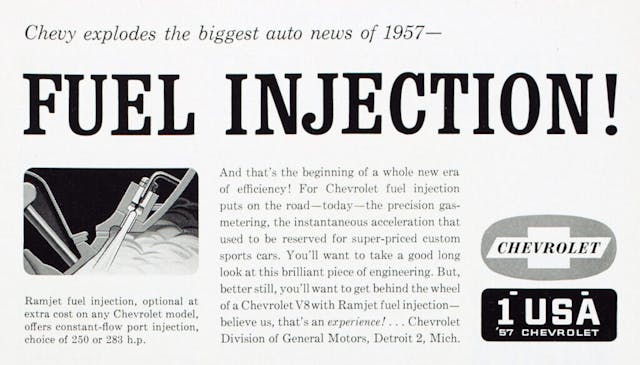
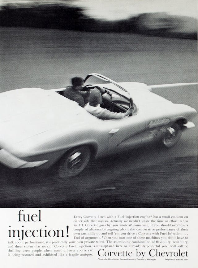
Rochester Ramjet fuel injection altered the automotive landscape in 1957
In the mid-20th century, fuel injection was still largely the stuff of fantasies. Then General Motors shocked the automobile world and put injected Chevies and Pontiacs on the showroom floor. Car-loving performance enthusiasts drooled, and the Beach Boys sang about a “fuel-injected engine sittin’ under my hood.” It was automotive culture shock. We were accustomed to seeing that technology on race cars, but fuel-injected cars that you and I could drive? That was other-worldly.
Although the Rochester Ramjet fuel-injection system that premiered in 1957 on Corvettes, full-size Chevrolets, and Pontiacs moved musicians to song, it wasn’t long before it had mechanics tearing their hair out, and, on occasion, replacing the pricey injection system with a carburetor or three. Although Rochester FI is relatively simple in concept and includes only three main components—an air meter, a fuel meter, and a manifold—it is a unique design rife with hidden complexities, multiple versions, a long parts list, and an abundance of pitfalls for even skilled mechanics.
Today, fuel-injected GM cars of the era are rare and expensive collectibles. A quality restoration of any of these mid-century classics must include the rebuilding and tuning of the fuel-injection system. While a knowledgeable DIY mechanic might attempt the job, most will want to farm it out to a skilled tech in order to get the fuel-injection system functioning as it should. No matter who does the job, it’s best that the car’s owner understands how the system works.
Fuel-injection—pressurized fuel delivered via nozzles and a pump—made its debut on 19th-century diesel engines. During World War II, injection systems fueled aircraft engines. Postwar, Mercedes-Benz had implemented a timed injection system on its 1953 300SL, which borrowed largely from diesel systems. But the technology was still foreign to most American buyers when GM introduced it.
At its heart, the Rochester system is constant-flow fuel injection, not unlike the fuel-injection systems manufactured by Hilborn and others that drag racers have used for more than 70 years. Like those systems, it constantly delivers fuel under pressure to nozzles in the intake runners.
The Hilborn system uses a return line in the fuel system to send some fuel back to the tank and thereby regulate mixture. An orifice or “jet” in the return line determines how much fuel will be returned, allowing only a specific amount to be delivered to the nozzles. Because dragsters operate almost exclusively at wide open throttle, mixture can be regulated by that single jet. A simple valve attached to the throttle linkage controls fuel delivery at idle. But these “on or off” fuel delivery systems are undrivable on the street.
The Rochester system also utilizes a return line to regulate mixture, but rather than controlling return-line flow with a single orifice, the Rochester uses a moving valve or “spill plunger” that opens and closes a spill port to the return line in proportion to the needs of the engine at various throttle openings and load conditions.
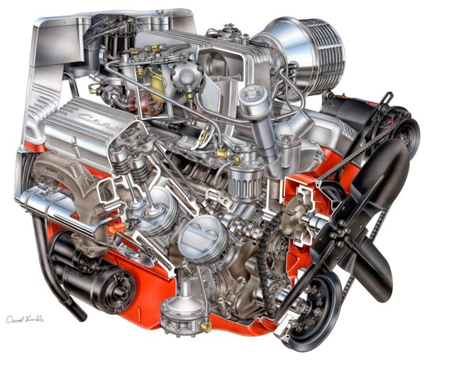
A conventional mechanical fuel pump delivers fuel to a reservoir at the base of the fuel meter. A float system, like that of a carburetor, regulates fuel level in the reservoir. A gear pump in the reservoir is driven at half engine speed by the ignition distributor and delivers pressurized fuel to the fuel meter.
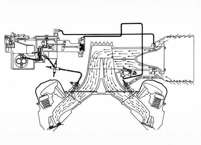
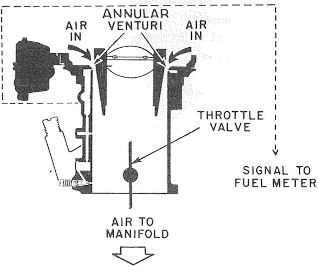
The system determines engine fuel requirements by measuring vacuum at two locations—in the intake manifold and at a venturi in the air intake. The vacuum levels sensed at the intake venturi and manifold determine how much fuel should be delivered to the spider fuel distributor, directed to eight fuel lines, and injected into the intake ports by eight nozzles, one above each intake port.
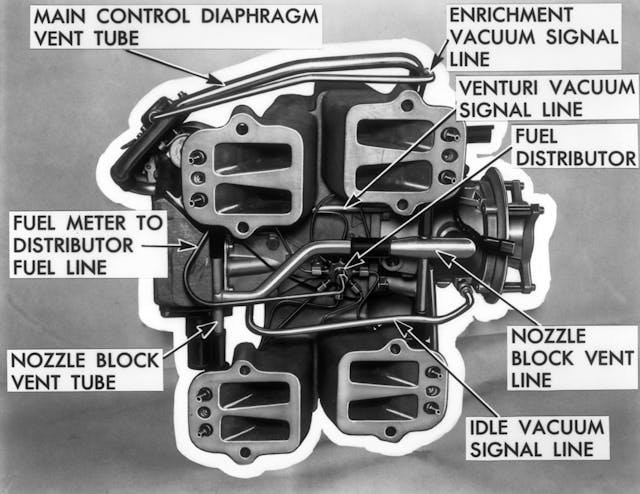
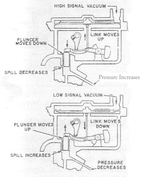
Vacuum at each location is measured by a diaphragm. A relatively small enrichment diaphragm measures the strong manifold vacuum signal, and a large diaphragm measures the weaker venturi signal. The venturi vacuum signal is a direct measure of air flowing into the engine at any throttle position above idle. The venturi vacuum diaphragm is linked to a fuel control lever. That lever is in contact with the spill plunger and moves it up and down, opening and closing the return line spill port and regulating the amount of fuel delivered to the nozzles. How much force the fuel control lever can exert on the spill plunger at any given time is determined by manifold vacuum.
Manifold vacuum, which varies in respect to throttle opening and load, acts on the smaller enrichment diaphragm, which actuates an enrichment control lever. (The enrichment control lever is called the ratio lever in early GM documents.) When the enrichment control lever changes position, it alters the pivot point of the fuel control lever, thereby varying the amount of force that is applied to the spill plunger. That, in turn, determines how far the plunger moves and how much of the return line spill port is exposed.
The enrichment control lever is where adjustments are made to fine-tune the air-fuel ratio. Rich and lean stops limit the movement of the lever. The lean stop determines fuel mixture at cruising speed with moderate throttle opening and high manifold vacuum. The rich stop comes into play at wide open throttle, when manifold vacuum is reduced. Both stops must be set accurately to achieve good performance.
The above covers only the basics. Supporting systems, like cold-start and cranking detection are important as well, and their function varies by model year and even system part number. Anyone attempting a restoration must come to battle heavily armed with knowledge and documents.
Jack Podel, of South Bend, Indiana, is among the few highly skilled techs who still specialize in Rochester FI. Podel notes that he doesn’t rebuild fuel-injection systems; he restores them to like-new condition. He says that many skilled DIY mechanics try to repair the system, but a lot of them end up shipping their failed attempts to him. Part of the problem, he says, is that most systems have been repaired in the past, often incorrectly or with the wrong parts. So, when you disassemble the unit, you can’t be sure that what you see is what GM intended. While the system was produced for only nine model years, from 1957 to 1965, 20 different part numbers were assigned. Podel says that among them, he counts 16 significantly different systems. And though all systems are conceptually straightforward, each includes hundreds of small parts, all of which are subject to deterioration over time, and many of which are specific to one model year.
John DeGregory, a Pennsylvania-based tech who is also a highly respected restorer of Rochester FI systems, offers a bit more encouragement to DIY fuel injection techs, but he says anyone attempting the job must be educated or they’ll do some damage. Both Podel and DeGregory will assist those who have problems over the phone, and each offers a wide range of replacement parts.
If you’re going to try to do it yourself, you’ll need a factory manual and some secondary references. Because the systems have so many differences, your primary source should be the appropriate GM manual. Reproductions of most can be purchased inexpensively online. But the factory manuals are best supplemented with the advice of experienced techs. A good secondary source, like Jerry Bramlett’s Ramjets that Run! can be very helpful as well. Bramlett was a leading Rochester FI tech for many years but is now retired.
Parts are available from a few providers who still doggedly deal in the restoration of these systems. Among them are Podel, DeGregory, and Jim Neuffer. All are listed below. It’s recommended that parts be purchased from an expert source—that’s the best way to be reasonably sure you’re getting the right part.
Rochester Ramjet fuel injection was a milestone achievement for the U.S. auto industry, and the injected GM cars that have survived are esteemed classics. Restoring one of these automobiles correctly is both an obligation and an honor.
Rochester Ramjet Parts and Service
John Podel: (574) 232-6430
John DeGregory: (724) 832-3786
Jim Neuffer (Parts Only): (585) 637-9562, 11 a.m. to 11 p.m. ET
***
Check out the Hagerty Media homepage so you don’t miss a single story, or better yet, bookmark it. To get our best stories delivered right to your inbox, subscribe to our newsletters.

Fantastic article explaining a very complicated subject.
Good to have included the assistance contacts.
The artwork by David Kimble is great. We’ve seen his work before in these pages, yes?
I have seen a number of them at car shows but never knew how they worked. Somewhat similar to CIS (which I suspected)
Worked with an engineer who was on the project at Rochester Products. They were on so much overtime that when he went to cash his paycheck with his colleagues the back had to get more money from the vault,
The part of this system that I don’t understand is that it shoots fuel into all 8 injectors at the same time. Doesn’t fuel build up on the closed intake valves and then dribble in when the valve opens?
There is not enough time for fuel to pool.
This is also the generally what grouped double-fire multi-point fuel injection did for years
Bosch CIS injection works the same way, as do carburetors, in a general sense. Most non direct injected FI also does so – the injector is pulsed on and off totally independent of the intake valve, as the length of the “on” pulse controls how much fuel is delivered.
I started racing a 1959 Corvette with FI in 1963 with Cal Club. I had to learn very quickly about the system. My first attempt caused me a blown engine as I got it too lean. Doug Hooper was very helpful in teaching me how to work on the FI. Later I ran the Bill Thomas dual air meter FI on my Cheetah. The units are very dependable and adjust for weather conditions. The real limitation is that the air meter only flows 580 cfm which is the reason that Bill Thomas and Zora modified the units for racing.
Very neat article on the RamJet Fuel Injection system.
“Anyone attempting a restoration must come to battle heavily armed with knowledge and documents.”
Truer words have seldom been written. You’ve made a very interesting and instructive piece here, Mr. Stenquist – thanks!
When they came out I, like millions of other gearheads, looked under hoods and lusted (a different lust than for, say, Gina Lollobrigida – but nonetheless, it was true lust) to possess such a marvel. When some of them found their way into the ranks of my local crowd, we soon learned that they were a lot easier to look at than to try to maintain (you can draw your own conclusions regarding Ms. L.) – and when one got cranky, there wasn’t a shade-tree mechanic in town that could tame it. And frankly, even the trained techs at the Chevy dealership were only moderately competent at the time.
I still “ooh and aah” when I see one of the old Rochester units sitting atop a small-block, but like plenty of others, nowadays I would only want to own one to display and entertain offers on. There are plenty of much more efficient (and less expensive) options to actually feed fuel to my engines these days! However, having said all that, I think this is an important and relevant article, and I will save it in my archives…😁
Remember the Fuel injection well it was something legends were made of back in 57. FORD also had the answer to the Chevy. FORD came out with their answer to the performance of the Chevy, In 1957 FORD had a supercharger. How it is fair against the Chevy I don’t know. The way you could tell, FORD installed Edsil tail lights on the 57 FORD.
The 1958 Edsel line was introduced in the fall of 1957. So how could any 1957 Ford have Edsel taillights?
John DeGregory is an expert, and does great work. After an earlier restoration by one of the others mentioned, my ’65 unit never ran properly, and finally failed miserably. Later it was determined that the ratio lever was installed poorly, not to mention a few other details like using some kind of “caulking” for seals. I had it professionally rebuilt by George Schreffler in Harrisburg, PA following a referral from the NCRS. A new ratio lever was installed, new seals were properly installed, and the unit was calibrated and test run on an engine stand. Perfection!!
Ahha in the old days I remember driving by the Rochester Products factory on Mount Read Boulevard back in Rochester. Knowing that they were building something special but I only had enough money for a 56 Chevy with six twos and other over the counter speed parts bought from Hallman Chevrolet. The article brings back good memories.
In about 1967, I installed a Muntz 4 and 8 track tape player into a 1964 corvette coupe for a fellow college student. A week later he called me, asking if I could find a 4-bbl carb and manifold to replace his Rochester FI unit. One junkyard visit and 8 hrs later, he gave me $100 and the suplus Rochester FI unit (including the tach and FI drive distributor). Two months later, my ’62 Impala SS had a Chevy long block 327/350hp motor (hyd lifter) and BW-T10 to replace my original 283/175hp powerglide drivetrain. I bought the manuals and replaceable parts kits and had that motor purring at 20-22 mpg on 70-75 mph travel. I still have all the parts from that car which I FOOLISHLY lent to my bro-in-law who didn’t REALLY know how to drive a stick shift; I have a ’65 vette which will look good with that original ‘pink-rod’ replacement motor. (BTW, like Kodak Ektachrome color film and LOTs of chemical industry technology, the Rochester FI technology was plundered from Nazi Germany following the May 1945 surrender. Bosch, Zenit carburetor other contractors developed the multi-diaphragm ‘Luftmetrik’ vaccuum signal FI system for the Junkers Jumo V-12 210 aircraft engines (for transports, bombers and other A/C which were not rated to fly upside down); in actuality, that multi-diaphragm system ran on test engines, but the Luftwaffe changed the requirement to direct injection FI like Daimler-Benz had always championed. Dow, DuPont, GE, Ford, GM, Kodak and dozens of other American companies sponsored ‘technical evaluation’ teams into post-surrender Germay looking for free technology; to the victors go the spoils.
a great article ! THANKS f0r posting as i always wondered how it worked!!
No mention of the Pontiac units that I recall being on at least the 1957 cars. The cast aluminum airbox was a different shape. Was hoping that there might be some mention of an experimental that was built for an earlier than 57 Cadillac engine. I recall that these Rochester units were commonly available as apparently many took them off their engines to replace them with carburetors as they could not correctly tune them. My local speed shop had shelves of them at $75 for the earlier style units and $200 for the later style 63+. The smart guys where those who were buying them up but not likely until years later when they were a bit more than $75. I had a unit I bought at $75 and put on my 57 chevy that I later sold apart from the car. Many years later I found the original fuel filter casing that I forgot to include with the injection unit. I sold that for the same price that I had paid for the whole unit and I think that was even too cheap at the time.
No mention of the cable connecting the distributor to the gear pump and how they used to snap and leave you stranded. My idiot cousin had a 65 fi whose cables snapped so often that he kept a stack of them in the glove box.
Also, no mention of the fragile fuel lines that broke off at the intake manifold connections. I crewed for my friend “Big Al” whose fi vette qualified for the BP SCCA runoffs at Daytona in the late 60’s. A few laps on the bumpy infield course cracked half of those fuel connections. He came into the pits spurting gas all over the place, was lucky not to catch fire. I crimped new ferrules on the ends, bent the lines back into the manifold, sent him back out only to have him hit the wall. He had wondered why he was the only one using the fi “extra hp advantage”. Now he knew.
Podel,DeGregory,Grata and of course the late Jim Thorpe are people to get advice on the Chevy fuel injection ! Great advice!