Bench-testing an instrument cluster
One of the dynamics in the Hack Mechanic household is that the number of guitars rivals the number of cars. Fortunately, the guitars are considerably less greasy and a lot smaller, all fitting in one room. While I haven’t bought any new cars recently, I have bought two more guitars. I didn’t need either, but sometimes, like with cars, circumstances present themselves—an instrument speaks to you, you bond with it, and you act. (Which is, of course, a heartfelt and carefully-crafted description of an utter lack of self-control.)
To free up funds and make it seem like it’s a zero-sum game, I sold a few rare BMW parts. I had a pair of new-in-the-bags European-style flush turn signals for a BMW 2002. They’re no longer available and highly sought-after. I priced them slightly under the last available retail price, and they were snatched up immediately, which was the intent. Ditto with a pair of original chrome BMW 1600 front grills.
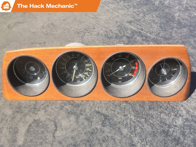
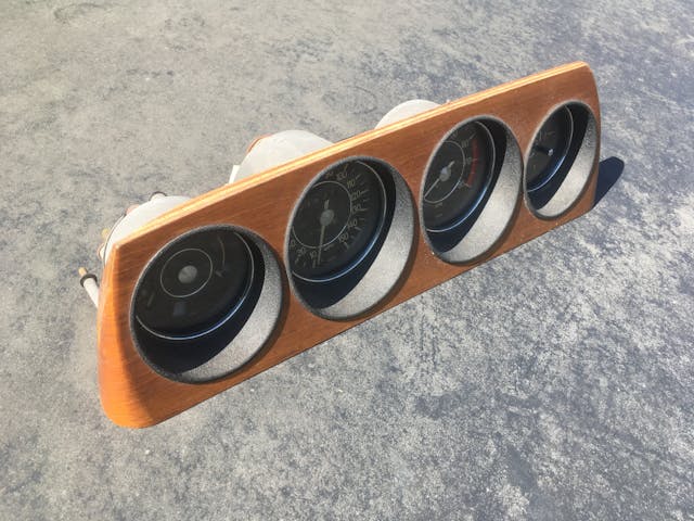
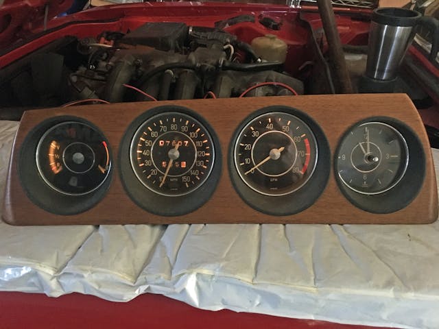
The last item intended to help fill the two-guitar-shaped hole in the bank account is a lovely wood-grained four-pod instrument cluster from a BMW 2800CS E9 coupe that I parted out over 35 years ago. It had been sitting in clean dry storage in my basement ever since. As with the other parts, I photographed it and researched the asking prices on eBay and enthusiast forums.
However, an instrument cluster is different from trim. It has electronics and moving parts. The descriptions I read for clusters with higher asking prices said that they’re tested and functional. My knee-jerk reaction was “I have no way to do that.” Unlike on a BMW 2002, where swapping out the cluster takes maybe 10 minutes, it is very difficult to get the cluster out of an E9 coupe.
And then a series of epiphanies occurred to me that enabled me to test the whole thing. The biggest one involves my steadfast belief that most of the time, you don’t need a wiring diagram, but we’ll get to that.
The speedometer
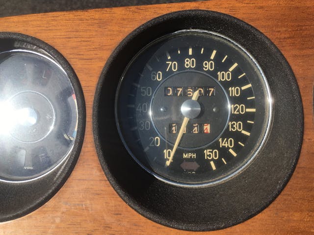
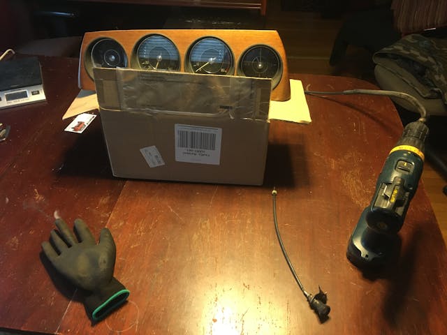
If the speedometer in the cluster is an old-school mechanically-driven unit, and you have a spare cable, odds are it can be easily tested by connecting the cable to back, gently clamping the transmission end into the chuck of an electric drill, and spinning it. Be certain to first check on an enthusiast forum for which direction to spin the drill, as you can damage the speedo if you spin it the wrong way. On a vintage BMW, you spin the drill in reverse. The whole thing took just a few minutes.
My rant about wiring diagrams
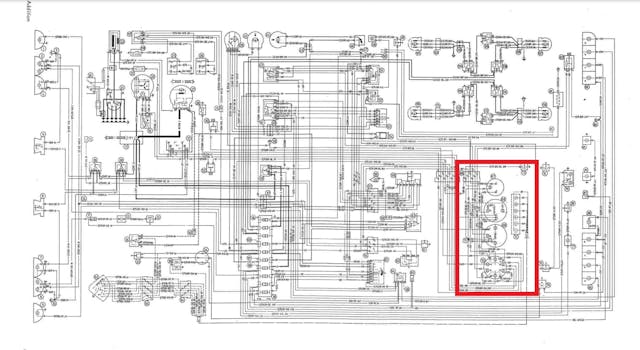
As I’ve said before, my experience is that the need for wiring diagrams on vintage cars is overblown. Sure, there are times when you do need to know what the green-and-red-striped wire in the multi-pin connector goes to, but most of the time you’re working from a PDF of a scan of a 55-year-old piece of paper in a shop manual, and it’s very difficult to read. On German cars, the wiring diagrams generally label the wire colors and the so-called “DIN” standard numbering of the terminals, but the components, much less the common-sense functions of the individual connectors, may not even be labeled, and if they are, they’re likely in German. If you need to know—oh, let’s just pick some example at random—the individual connections on the back of a gauge cluster, it’s often easier to look on an enthusiast forum and find a photo where some kind soul has labeled them with their actual useful names. Below, I’ll explain why not even that was necessary for me to test the gauges.
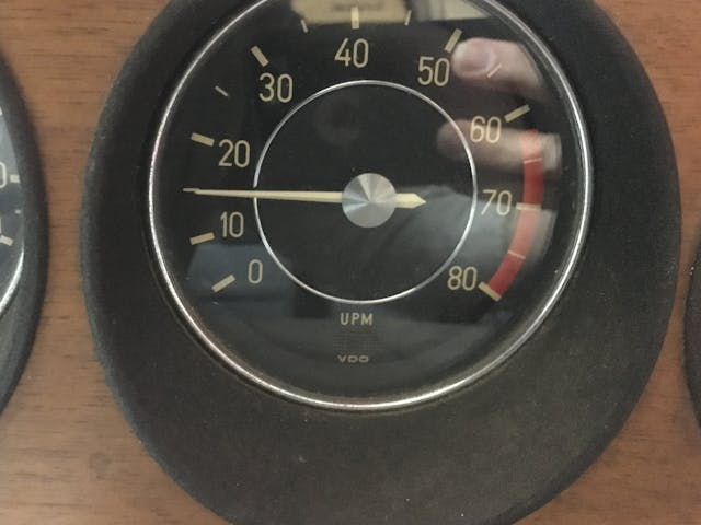
The tachometer
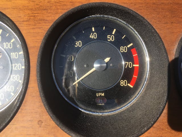
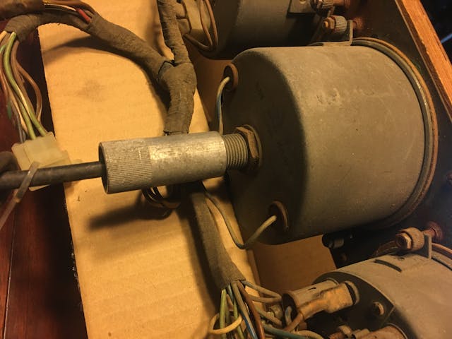
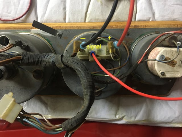
Tachs on vintage cars generally have three wires—power, ground, and a signal from the negative side of the coil (the side connected to the distributor, often stamped “1” or “-”). I could tell which of the three connections on the back of the E9’s tach were which because the power and ground connections were labeled as “+” and “-“ and were shared with other gauges, and the wires on the ground connection were the standard German brown, which left the third unshared unlabeled connection as signal.
For this test, I opened up the hood of my E9 coupe in the garage, laid the spare cluster on a pad, took the red and black test wires I carry with me on every road trip that have small battery clamps at one end and female spade connectors at the other, connected them to the car’s battery, and connected the ends to the power and ground male spades on the back of the tachometer. Then I took another wire with female spades and both ends, connected one end to the negative side of the coil, and the other to the signal input spade on the tach, and started the car. The tach sprang to life.
Fuel and temperature gauges
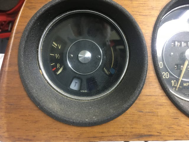
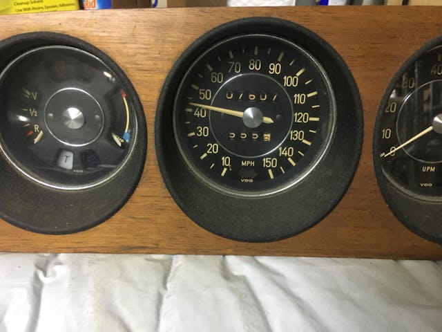
As is the case on many cars, the fuel and temperature gauges on the E9 are part of a gauge pod with other functions such as the high beam, brake, oil pressure, and battery warning lights. Initially, when you look at the back of the gauge, you think “How do I tell which connection is which, much less test things?”
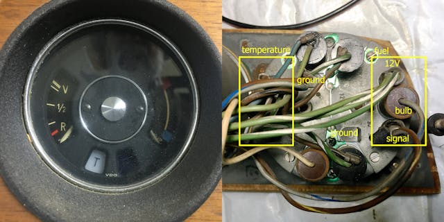
But it’s actually not that hard. The trick is to simply look at the front of the gauge, note which function is where, flip the gauge around, and match things up. In the composite photo below, you can see that the gas gauge is on the left, so when you turn the cluster around, it’s actually very clear where the wires and connectors on the right for the gas gauge are. It’s obvious that the big circular one is the bulb. The multiple wires on the spade connector above it are the shared power (there’s also a little “+” above it). That means that the single wire on the spade connector below the bulb is the signal for the gas gauge. The same is true for the temperature gauge on the left, but its terminals are obscured by the bend of the wires in the harness.
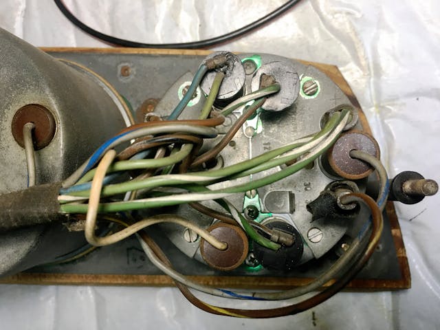
The ground is a bit harder to see in the photo. The metal cases themselves are ground for each of the gauges. There are two male spade connectors that stand upright from the back of the case. The one at the upper left has chassis ground passed to it through the wiring harness. The one at lower center is unused, making it a convenient attachment point.
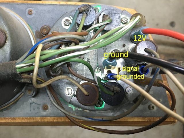
The last trick you need to know for this benchtop test is that temperature and fuel gauges and senders typically work by having the gauge interpret a variable resistance between it and ground. If there’s infinite resistance—no connection to the sender—then the needle doesn’t move, so the fuel gauge reads empty, the temperature gauge stays at the bottom. But if there’s low resistance connection between the gauge and ground, then the needle pegs (full fuel tank, temperature high in the red). The lowest resistance is continuity—grounding the signal connection. So to check functionality of these gauges, all you need to do is apply power and ground and make sure the needles are sitting at the bottom, then ground the signal connector. In the photo below, the bundle of green and white wires have been pulled off their male spade post, replaced by a thick red wire connected to battery positive. A Y-adapter has been connected to the spade for the case ground. The thick black wire is connected to battery negative. A white jumper wire connects the fuel gauge’s signal input to ground.
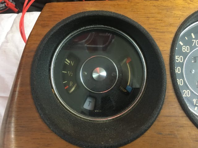
And … ta-DA!
I repeated all this to test the temperature gauge, with the same results.
With the gauges all tested, the only task remaining was to turn the cluster lights on. This was less to test them than it was to get the pic of the glowing instrument cluster because a) it would carry visual impact that the cluster was tested and worked, and b) it would be cool. For this, since the bulbs are all tied together, the easiest way to do it was to look at the wire color they used (gray and blue), find the pin on the harness connector using that color, feed it 12V, and use a shared ground for the instrument cases.
So, I now have a tested E9 gauge cluster. It hasn’t sold yet, so no more guitars (or cars) for this guy. Unless I find one that, you know, really speaks to me.
***
Check out the Hagerty Media homepage so you don’t miss a single story, or better yet, bookmark it. To get our best stories delivered right to your inbox, subscribe to our newsletters.
Excellent column!
Well-explained and easy-to-follow descriptions; (love my hyphens.)
Was the clock intentionally not mentioned?
Sorry, I thought I said that I tested the clock first as it was the easiest, and it didn’t work. I fixed the clock in my own E9’s cluster about ten years ago by replacing an internal capacitor.
I have two classic cars and a few guitars. So what guitars are in your collection?
Rob great article and easy to follow instructions. If your loyal readers do not hear from you until the new year. Thank you for your excellent stories and repair tips through your the year and Merry Christmas and have a safe a joyful time off.
Thank you!
On some cars – at least Mopars of musclecar-era vintage – gauges use a 5V limiter; in which case, don’t connect 12V directly to those gauges.
Yes, by all means this needs to be checked, thanks.
So which two guitars spoke to you?
There are a couple that are speaking to me right now, but I lack any valuable old car parts, so I can’t reply to them…
Agreed: Rob, need more info on the guitars and what language they are speaking… 🙂
See below.
Yes, need more guitar info, lol!
Okay then!
–A 1970 Guild D40 that looks just like the ’71 D40 I bought with my bar mitzvah money and owned for three decades, but plays and sounds WAY better as it was built before Guild began beefing up instruments. It’ll be the “strummer” that I leave out so I always have something to grab and play.
–A 2005 Northwood MRS80 mini-jumbo with Madagascar rosewood sides and back in like-new condition, an astonishingly nice fingerstyle guitar.
Spade connectors are not what you had on those gauges. They are called quick-disconnect terminals. Spade connectors resemble a fork with only two tines and are normally held down under a screw head on a connector strip made of plastic or phenolic board.
You are correct, but quick-disconnect connectors ARE commonly referred to as spade connectors in the automotive world, and I’ve given up fighting this particular fight.
Rob, sprak with Jack (your former editor inchief) he has a whole basement full of guitars and is culling his stock pile. I am sure you could work it a trade in time instead of money as a pit mechanic or pit crew member. He has something called a Radical 8 that seems to need a rebuild after every race.😂😂😂
When bench testing a mechanical speedometer and don’t have an old cable, take a short length of household 8 or 10 gauge wire (often used for grounds) an hand file one end square till it fits in the speedo’s drive slot. Chuck the other end in your cordless drill and have at it. Just make sure you run it in the correct direction.
Great info in here (article + comments). I’ve related this story before, but once I sat two clocks on the bench – the one on the left worked and I planned to use it to replace the non-functioning one (on the right). After detailing it up (repainting the hands, buffing the plastic cover, etc.), I promptly sat it on the to the left and went in to supper. Yep, next day I installed the non-working clock in my cluster and the cluster in the dash. The “good” one is now in a box on a shelf and the one in the car thinks it’s ten minutes ’til two all day, every day 🥴…
I have an early BOXSTER and I can assure you that it has an instrument cluster very different from the critter you dissected. Also, the only way I know to remove. tinker with, and replace it is to use a crowbar or a fire axe (or both), and at 81, I’m not about to try the job. Interesting article though; reminds me of the series of 356’s I owned over the years.