Wrenchin’ Wednesday: DIY short circuit tester
Wiring can be one of the toughest systems to diagnose. Mechanical systems, with their physical nature of moving parts that produce observable cause and effect, can often be sorted as easily as a dollar store puzzle. That wiring though, with those invisible electron pixies dancing inside their copper corridors? Witchcraft!
Well, until you have the proper tools, anyway. Voltmeters and test lights are common pieces of equipment, but for today’s Wrenchin’ Wednesday, we’ll piece together a simple short circuit detector that greatly speeds up the diagnostic process. It’s especially useful for intermittent failures that only show up while you’re trundling through traffic rather than hanging under the hood.
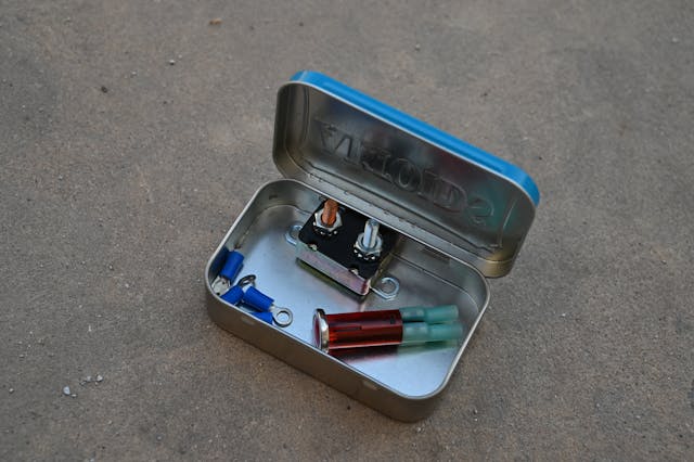
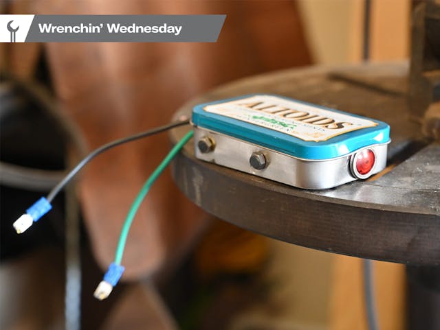
The parts list here is simple: You’ll need some kind of enclosure—a venerable box of Altoids is my solution, though my father’s preference (as a Cadillac technician in Texas) was a can of Skoal. Really anything works here as long as it can fit a generic 10- to 15-amp breaker (post or blade terminals are fine) and a light bulb that’s rated for as much or fewer amps than the circuit you’re testing. The bulb will act as a fuse, so avoid grabbing any old high-amp bulb, as it may sustain a flow of current that is unsafe for the circuit. Scrounge up the terminals and wiring that fit your components, too.
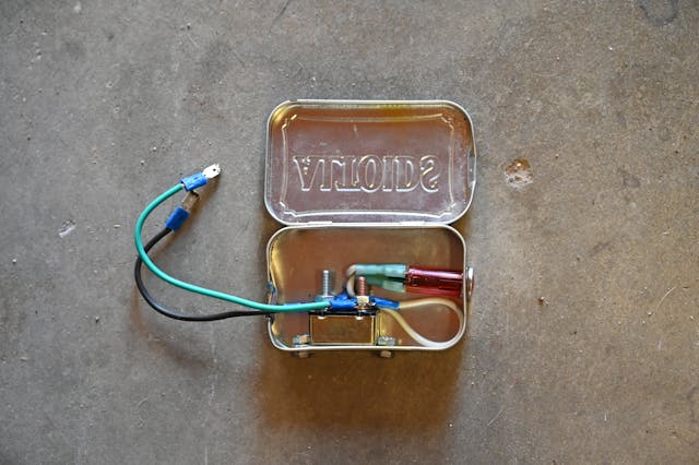
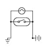
In short, the breaker and the bulb are wired in parallel to a pair of leads, which creates two paths for electrical current to flow through, but it will only do so under the law of attraction to either the bulb or breaker depending on the state of the fault. I’ll include a simple wiring diagram (above), but the only thing that really matters for proper function is that the leads to the breaker are wired in the correct polarity, so make sure to have a color-coded wire to ID the positive and negative wires so that the short detector you’re building isn’t hooked up backward.

To use it, either place the detector in series/inline with the positive feed of the circuit or attach blade terminals to the leads which match the terminals in your fuse block. During the no-fault condition, power flows through the breaker harmlessly and the circuit is powered as usual. Once a short happens, the breaker does its duty to open the circuit up, which causes power to then flow instead through the resistive light bulb, indicating the fault.
The system also does two things to continue safeguarding the circuit: First, an incandescent light bulb is basically a fuse that gives off light at a certain current load, beyond which the filament melts and stops the flow of power as the bulb burns out. Second, it also ends the short circuit by giving the current someplace to dissipate instead of generating heat alone in the wiring in a pure short, which is what ultimately melts wires and creates any number of fire hazards.

