Troubleshooting a crankshaft position sensor
It’s often said that a car needs fuel and spark to start and run. That’s true, but it needs other things, as well: air, compression, and in-the-ballpark timing. Nitpicking aside, it’s still an incredibly useful adage for vintage cars, meaning (to me) 1974 and older. However, the newer a car is, the less useful the “fuel and spark” adage is. That’s because although the presence of that holy duet is still required, the car’s increasing complexity means that the list of things that prevent fuel and spark from happening becomes longer.
In 1975, federal emissions standards underwent a step change. The new, stiffer requirements were satisfied by unleaded gas, catalytic converters, oxygen sensors, and lean-running engines, but many cars were low on power and ran poorly. By the early 1980s, many manufacturers had adopted electronic fuel injection (EFI) as the best way to achieve a compromise of emissions, power, and fuel economy. By the end of the 1980s, most cars had jumped on the EFI bandwagon.
From the get-go, all but the most primitive EFI systems employed a crankshaft position sensor, also called a crank angle sensor (abbreviated as either CPS or CKP), to tell the car’s electronic control unit (ECU) where the engine is in its rotation cycle, so it knows when to fire the fuel injectors and time the spark.
Fast-forward to 1996, at which point all cars sold in the United States were required to adopt the so-called OBD-II diagnostic system, where a standard code reader can be inserted into a standard plug and read trouble codes in the car’s emissions monitoring system. While there are many trivial emissions issues, evaporative leaks and such, that will throw a code and cause the dreaded check engine light to be illuminated while not affecting drivability at all, one of the most likely problems to suddenly cause a no-start condition in a modern car is a bad crankshaft position sensor, and that also will throw a code. So if your car is a 1996 or newer model, the most common method of diagnosing a bad crank sensor is to plug in a code reader, read the fault code, and see if the crank sensor is listed as the culprit. However, if you have a pre-OBD-II car, you’ll have to diagnose it yourself.
How the crank sensor branches off the troubleshooting tree varies from model to model. On most cars, it’ll affect both spark and injector firing, but on others, the ECU must see the crank signal in order for the fuel pump to run at all.
As with other rotation sensors, such as ABS or wheel speed, there are two basic types of crankshaft position sensors. Most pre-1996 cars use a passive sensor called a Variable Reluctance Transducer (VRT). A stationary magnet is wrapped in a coil of wire, and a rotating toothed device called a reluctor wheel passes near it. For a crank sensor, the reluctor wheel is often the flywheel itself; the sensor is often reading the teeth or other reference marks on the flywheel. As the teeth pass near the magnet, they affect the magnetic field. Since a changing magnetic field creates an electric field, the motion of the teeth past the sensor creates a roughly sine-wave-shaped up-and-down signal. As the flywheel spins faster, the peaks on the signal not only get closer together, they also get stronger. Typically, when a VRT is employed as a crank sensor, one or more teeth on the reluctor is missing, creating a gap in the signal that the car’s ECU then senses at Top Dead Center (TDC) for cylinder #1.

Some cars employ two separate crank sensors—one that senses only TDC and another that measures the actual rotation. In this case, the first is usually called the crankshaft reference sensor, and the second may be called the crank angle or crank speed sensor.

The other type of sensor is the Hall Effect sensor. There are a few flavors of these, but modern examples generally employ a ring of magnets pressed into the rotating component. A semiconductor in the Hall Effect device senses the magnets as they pass, and integrated electronics clean up the signal and output it as a square wave. Hall Effect devices largely replaced VRTs sometime between the mid-1990s and the early 2000s. They’re usually smaller than VRTs and less prone to interference.
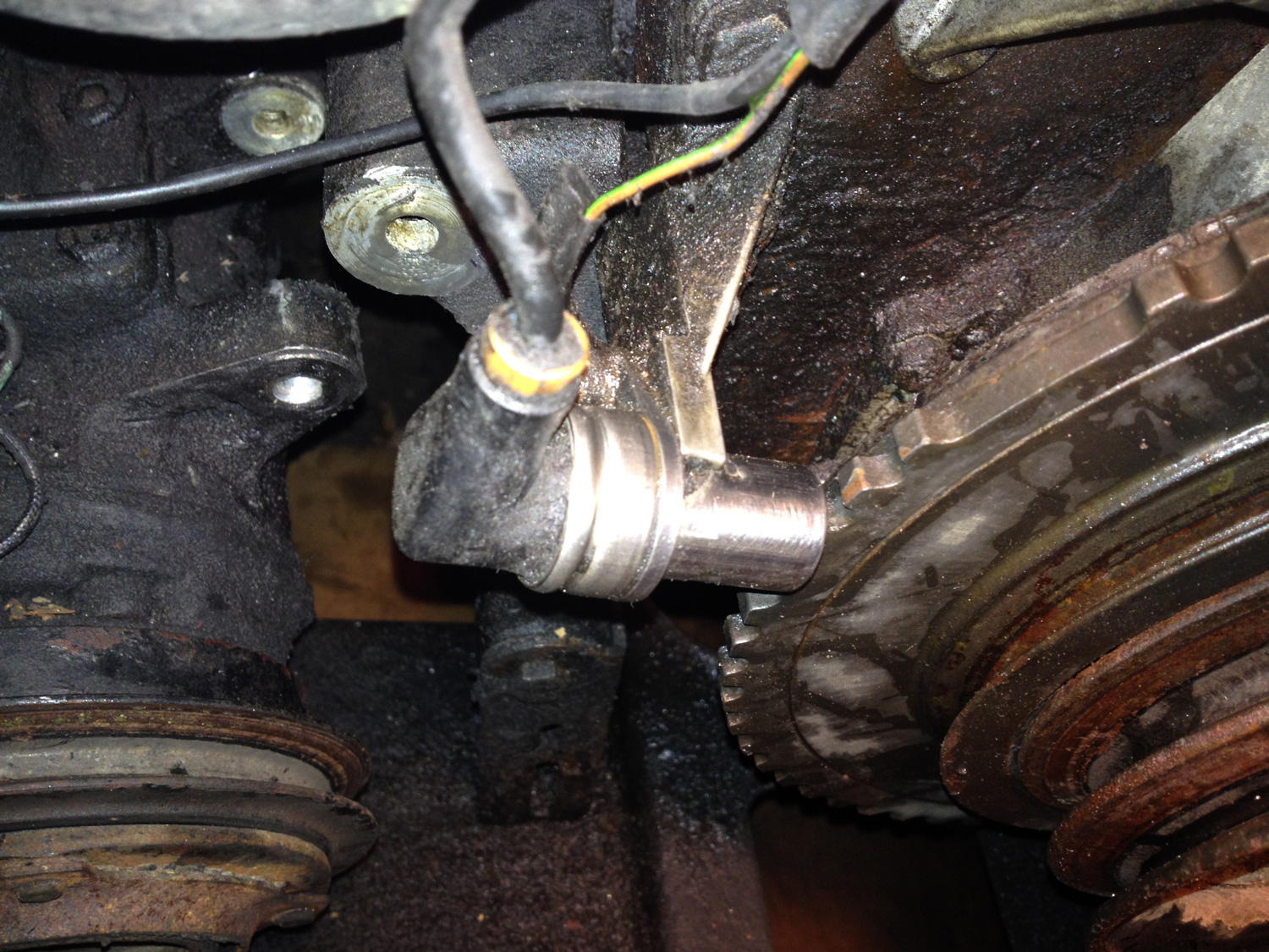
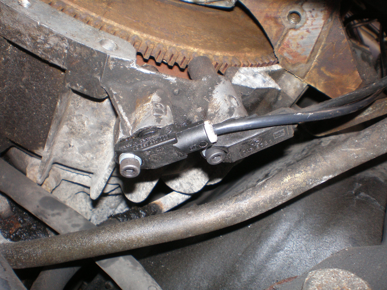
The first step in troubleshooting a crank sensor is physical inspection. The sensor is at either the front or the back of the crankshaft, so it’s usually located either on the transmission bellhousing or behind the crankshaft pulley. There should be a small air gap, usually about a millimeter or two, between the sensor and the reluctor. So if the sensor has been dislodged, or its mounting bracket has cracked… or the bolt holding it has backed out, that can knock the signal strength down and cause failure.
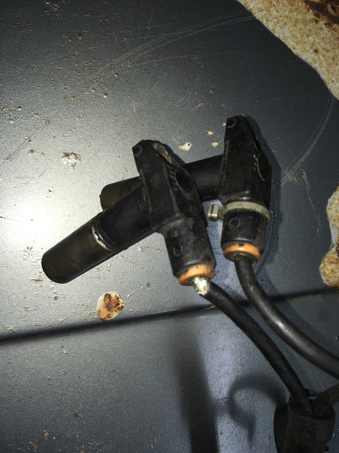
Next, carefully inspect the wiring. Heat and leaking engine oil can do a number on the cable into the back of the sensor. Then follow the cable back from the sensor to where the connector mates with another connector on the wiring harness. Sometimes the connector is part of the body of the sensor itself, but often there’s a pigtail. The connector may be dislodged or cracked, or the mating pins may have pushed out the back, or corrosion may have crept in. Sometimes simply re-mating the connector solves the problem.

If inspection doesn’t reveal and solve a problem, testing is next. The ease with which you can directly test the crank sensor itself depends on which type you have. If it’s the older passive VRT-style that most pre-OBD-II cars have, you can directly test it, but if it’s the later three-wire Hall Effect sensor, most people simply rely on plugging a code reader or scan tool into the OBD-II socket and looking for a crankshaft sensor-related fault.
Let’s look at the VRT sensor first. Because these are passive sensors, they don’t require power, so there are often only two wires—signal and ground. However, some VRT sensors have a braided sheath inside the cable to shield the signal from interference, and that sheath may have a third wire on the connector. If you have any doubt as to which kind of sensor you have, set a multimeter to measure DC voltage, disconnect the sensor at the connector, connect the black meter probe to chassis ground, crack the key to ignition, and touch the red probe to each of the pins on the wiring harness side of the connector. If one of them reads in the neighborhood of five or 12 volts, it’s a Hall Effect sensor. If none of them do, it’s a VRT.
You may have been told that the best way to test a VRT-based crank sensor is to take a multimeter and measure the resistance between the signal and ground pins of the sensor. After all, the sensor is simply a coil of wire wrapped around a magnet, and the resistance of the wire should be low, about one ohm or less. If the resistance is infinite, there’s clearly a broken wire in the cable or the coil, and the sensor must be replaced. You can do this, but it isn’t a definitive test, as all that this tells you is the wire isn’t broken. It doesn’t tell you whether the sensor and reluctor are working together.
The cool thing about a VRT is that, because it’s an analog sensor that outputs a sort-of sine wave, the signal itself should be detectable as an AC (alternating current) signal. So, take a multimeter, set it to measure AC voltage, connect the red and black multimeter leads to the sensor’s signal and ground pins, and crank the starter motor. You should see an AC signal on the multimeter. If your meter has a “Hz” button, you should be able to read the frequency of the signal. The exact signal strength and frequency don’t matter; what matters is that you should be able to see the presence of the signal when you crank the starter. If you don’t see anything, the sensor is probably bad.
For extra credit, if the engine is capable of running, if you connect the sensor cable and then back-probe the connector so you can read the AC signal on the multimeter, you should see both the signal strength and frequency (Hz) increase as the engine starts, then runs. (Of course, if the engine is capable of running, there’s probably nothing wrong with the sensor, but that’s why it’s extra credit.)
For a newer Hall Effect-style sensor, it’s more complicated. First, because Hall Effect sensors are active sensors, they require power. Thus, they’re almost always three-wire sensors (power, signal, and ground). You can check that voltage is present on the power wire when the key is cracked to ignition. As I said above, if you don’t know which wire it is, just use a multimeter set to measure voltage, connect the black probe to ground, turn the key to ignition, and check all three pins on the connector. One of them should be either 5V or 12V. If none of them are, there’s likely a break somewhere in the wire leading to the crank sensor. But because Hall Effect sensors don’t have a coil like a VRT, a resistance measurement across the signal and ground pins is meaningless.
To check for signal (because a Hall Effect sensor has to be powered), you’d need to plug in the connector, then back-probe it with the multimeter attached to the signal and ground pins while cranking the starter. However, you need to have a multimeter that’s capable of detecting a square wave, and most meters won’t do this. Some “automotive multimeters” that can measure fuel injector pulse width will work. The best tool of all, of course, is an oscilloscope, either a big bench unit or one of the small hand-held ones, but few DIY-ers have them.
So there you go. At a minimum, this helps explain why, even though folks rail against mindless parts-swapping, it’s so common for both DIY-ers and shops to troubleshoot no-start issues by throwing a new crankshaft position sensor into the car and seeing what happens.
***
Rob Siegel has been writing the column The Hack Mechanic™ for BMW CCA Roundel magazine for 33 years and is the author of five automotive books, including Just Needs a Recharge: The Hack Mechanic™ Guide to Vintage Air Conditioning. All of his books are available on Amazon. You can also order personally inscribed copies here. Siegel’s new book, Resurrecting Bertha: Buying Back the Car My Wife and I Drove Off From Our Wedding, will be released later this year.

