How to Use a Multimeter, Part 3: Measuring Resistance and Verifying Continuity
Last week, we showed you how to use a multimeter to measure voltage—or, more accurately, to verify that voltage is present—which is the most common reason you’d grab the meter and probe around in your car’s wiring. Now, we’ll tackle the second-most common use of a multimeter in a car—measuring resistance and verifying continuity.
As we discussed several weeks ago, resistance is the property of an electrical conductor that opposes the flow of current. In a load device like an electric motor or a light bulb, resistance is a good thing because it is actually taking the flowing charge and turning it into something useful, like a waterwheel in a river. In most wiring itself, however, you want the resistance to be as slow as possible to let the current flow through it without impeding it.
With that said, when we talk about measuring resistance with a meter, it isn’t the dynamic circuit resistance that we’re measuring; it’s the static resistance of a portion of the circuit.
Let me say that again in a different way. When a circuit is live, the voltage applied to the circuit, together with the total resistance of all of the components in the circuit, causes a certain amount of current to flow. You can measure the voltage and the current of a live circuit and use those figures to calculate the resistance (Ohm’s Law), but you can’t actually measure the resistance of a live circuit. For a number of reasons, you need to turn the power off and measure the resistance of individual pieces of the circuit. Or, to use the language we offered last week, a resistance measurement is taken with the circuit unpowered, in series with a portion of the circuit.
And, really, most of the time we’re not interested in the resistance value itself anyway. Instead, we’re usually interested in verifying continuity. (There are exceptions, such as testing a temperature sensor whose resistance varies with temperature, or verifying the correct resistance of a coil or a ballast resistor.)
So what is the difference between resistance and continuity? Think of it this way: Continuity is a binary version of resistance. If the resistance of the thing we’re testing—the wire we want to make sure isn’t broken, the connection we want to be certain actually goes to ground, the switch we want to know works—is low (like less than 1 ohm), we say that it has continuity.
Okay, let’s do a resistance measurement.
Configure the multimeter to measure resistance. There are three configuration steps:
- Put the black probe in the socket labeled “COM” for “common,” meaning it’s common to all measurements. Once it’s there, it’ll never need to be moved.
- Put the red probe in the socket labeled with the Greek Omega symbol (Ω) for resistance. It’s almost certainly also the same socket with the V for voltage. This means that you can leave the probe leads in the same sockets for the voltage and resistance measurements. You only need to change which socket the read probe lead plugs into if you need to measure current.
- Turn the big rotary dial to the setting for resistance, which is the one with the Omega symbol (Ω). If you don’t have an autoranging meter, select the most sensitive resistance setting. It’s really not going to matter much if you’re just looking for continuity. The meter should say “OL,” which stands for “over limit,” meaning that, with the probe tips not touching, there’s an infinite amount of resistance.
A multimeter configured to measure resistance (red probe in the “VΩ” socket, rotary dial turned to the resistance setting)

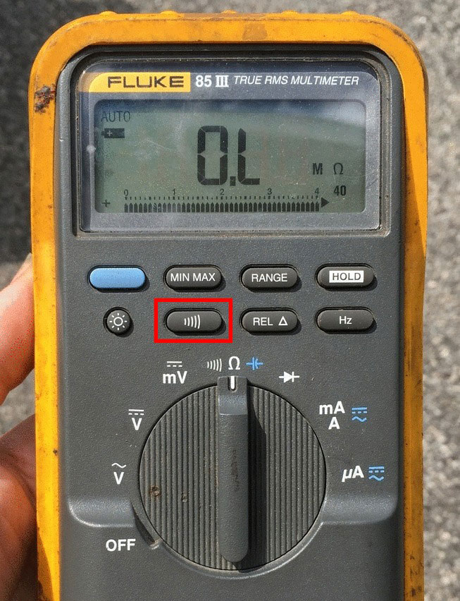
Configure the audible beep. If you’re testing continuity (and you almost always are), the “beep” is really handy, as it allows you to test without even looking at the meter. How to turn it on varies meter to meter. On some meters, it’s a separate setting on the rotary dial. On others, such as my old Fluke 85, it’s a button above the dial with a symbol that looks something like increasing sound waves or a megaphone.
The setting for the audible beep for continuity (red rectangle) varies meter to meter. On this one, it’s a push button

Test the meter. Now, touch the probe tips together. The resistance reading should drop from “OL” to near zero (meaning less than an ohm), and the audible beep should sound. This is what you should see when you put the probes on something that has continuity such as an intact wire or a closed switch.
The sub-one-ohm reading indicating continuity

Turn off the power! A resistance measurement must be performed with the power off. The way that a meter measures resistance is that it actually puts a small current across the probes and measures the resulting voltage. The resistance reading is meaningless if there is already voltage on the thing you’re measuring.
Isolate the thing whose resistance or continuity you want to test. For example, if you’re measuring the resistance between the “+” and “-” terminals on a coil, take all the wires off them first. That way you can be certain that you’re testing the resistance of the coil and not the wires running through the rest of the car that may be connected to other devices and to ground. If you’re verifying continuity between a terminal on a device and ground, it’s good practice to disconnect the wire from the device and connect the multimeter to the disconnected wire. Plus, that way, if the circuit is actually turned on without your realizing it, disconnecting the wire breaks the circuit and makes sure you get a valid resistance reading.
Here are some specific examples. The first is the one we just mentioned: Testing the resistance across an ignition coil. Note that we’ve removed the wires to ensure we’re not getting spurious readings from the rest of the wiring in the car.
The resistance of this ignition coil is 1.3 ohms

Next, we verify that the ground wire to a headlight is actually a valid ground (that it’s really connected to the body of the car, and then from there to the battery) by using the red lead to probe the ground wire on the headlight’s connector, and connecting the black probe to the negative battery terminal. The sub-one-ohm reading—and the beep—indicate continuity to ground.
Verifying continuity to ground

Lastly, we use the meter to check that a switch actually works by verifying that, in the “off” setting, there’s infinite resistance:

And that, in the “on” setting, there’s continuity (less than one ohm resistance, and a beep):

Now, you may find it surprising to learn that just because a meter verifies continuity, that doesn’t mean that the wire or the switch is capable of carrying enough current for the circuit to function. We’ll learn about that next week when we talk about measuring current.
Rob Siegel has been writing the column The Hack Mechanic™ for BMW CCA Roundel Magazine for 30 years. His new book, Ran When Parked: How I Road-Tripped a Decade-Dead BMW 2002tii a Thousand Miles Back Home, and How You Can, Too, is available here on Amazon. In addition, he is the author of Memoirs of a Hack Mechanic and The Hack Mechanic™ Guide to European Automotive Electrical Systems. Both are available from Bentley Publishers and Amazon. Or you can order personally inscribed copies through Rob’s website: www.robsiegel.com.


all the pictures are dead