How to Use a Multimeter, Part 4: Measuring Current (amperage)
First, we discussed how to use a multimeter for measuring voltage, or simply verifying that voltage is present. Last week, we addressed measuring resistance—verifying that a wire is continuous and not broken somewhere. Today we’re discussing how to use a meter to measure current, also referred to as amperage.
Let me say right off that measuring current is a far-less-common application than measuring voltage or resistance. For the most part, either a circuit works or it doesn’t. If it doesn’t, it’s usually because it doesn’t have a voltage supply (which is verified by using the meter to confirm the presence of voltage), it doesn’t have a path for the current to flow (which is verified by using the meter to confirm continuity), or because a part is bad. Thus, it’s rare that you’d need to independently measure how much current is actually flowing unless you’re trying to find the source of a parasitic drain that’s running down the battery. We’ll get to that at the end of this installment.
A current measurement is fundamentally different from a voltage or resistance measurement. To use the language we offered a few weeks ago, a current measurement is taken with the circuit powered, in series with the entire circuit. It’s like the water meter in your house—the entire water consumption flows through the meter so it can spin the vane inside it, which is used to measure the amount of water flowing. When you connect a meter to a circuit and use it to measure current, all of the current in the circuit flows through the meter.
It is also a measurement for which you need to reconfigure the meter—you have to move the red probe lead into a different socket than is used for the voltage and resistance measurement.
And, as you’ll see, there is typically a choice of two sockets. If you choose the wrong socket, or if there’s too much current, there is the possibility of blowing up your meter.
With those warnings in mind, let’s do a current measurement. Note that we use the words “current” and “amperage” (the unit of current) interchangeably, but the meter’s dial and sockets aren’t labeled with a “C” for current. They’re labeled with the letter “A” for Amperage.
Configure the multimeter to measure current. There are three configuration steps:
- As with all measurements, put the black probe in the socket labeled “COM” for “common,” meaning it’s common to all measurements. Once it’s there, it will never need to be moved.
- Put the red probe in the socket labeled with the symbol “A” for Amperage. On most meters, even autoranging meters, there are two sockets—a high-amperage setting and a more-sensitive, low-amperage setting. One socket may say “A” and have a rating of, for example, 10A (ten amps) printed next to it. The other may say “mA” for micro-amps and have a rating of, for example, 300 mA printed next to it. When in doubt, use the setting with the higher amperage rating.
- Turn the big rotary dial to the amperage setting that corresponds with the socket you’re using. This varies meter to meter. For example, there may be individual “A” and “mA” settings on the dial that correspond to the “A” and “mA” sockets, or there may be a single “A” setting on the dial. If you have any doubt, consult the documentation for your meter.
A multimeter configured to measure current on the high amperage setting (red probe in the “A” socket, rotary dial turned to the A setting)

Note that whether either of the two amperage sockets have an internal fuse varies meter to meter. On some meters, both are fused. On others, only the high amperage (10A) socket is fused. On many inexpensive meters, neither is fused. This means that if you, for example, connect the meter to a circuit with a 20 amp draw, you can blow up the meter.
You will sometimes read that to measure current you need to “splice the meter into the circuit.” It is exceedingly rare that you’ll need to “splice” anything in the sense of cutting a wire. You do, however, need to put the meter in series with the circuit, having all the current flow through the meter as if it’s a wire in the circuit, as depicted in the drawing below.
This is what is meant by the meter being in series with a circuit

Turn off the power before you connect the meter, and use alligator clips! Why is this important? When you use the standard pointy meter leads to complete the circuit when the power is on, all of the current of the circuit will immediately flow through the tiny tip of the probe lead. Due to the small surface area, the probe can heat up and micro-weld itself to what you’re testing. Using alligator clip leads spreads the electrical load over a larger area. Attach them, and then power the circuit.
Whenever possible, connect the meter on the ground side of the circuit. It’s the same reasoning you employ when, while replacing the battery, you should always disconnect the negative terminal first and connect it last. For a current measurement, the meter will be in series with the circuit, so the probe leads are as live as any wire in the circuit. If you connect the meter on the ground side of the circuit (as per the illustration above), completing the circuit to ground will cause power to flow if the circuit wasn’t turned off, yet it can’t cause a dead short of a live power wire to ground because the meter is already on the ground side. In contrast, if you connect the meter to the positive side of the circuit and accidentally touch a probe lead to ground, it’ll cause a dead short of power to ground, which is sure to blow up the meter’s fuse or the meter itself.
The photo below shows the meter measuring current on a small fan in a circuit that we’ve removed from a car for clarity. The positive battery terminal is connected to the positive terminal of the fan. The fan’s negative terminal is connected to the meter’s red lead, and the meter’s black lead is connected to the negative battery terminal. You can’t read the meter’s display, but it is showing about 5 amps.
Meter in series in a real circuit, measuring current

Note, however, that this kind of measurement is usually academic; it’s rare that you need to measure the current load from one device. In theory, an electric motor such as a fan or an electric fuel pump may have a higher amperage draw as it goes bad, but since you rarely know what an accurate “good” reading is supposed to be, this can’t be considered a definitive measurement.
Measuring current to find a parasitic drain and see what’s killing the battery
As state previously, the main application of a current measurement is to determine the magnitude and source of a parasitic drain—something remaining “on” that shouldn’t—that is killing the battery. To do this, the meter must be placed between the negative battery terminal and the body of the car, as you need to measure all of the current in all of the circuits.
The time-worn advice on how to find a parasitic drain is to connect the meter as described, pull out fuses until you see the reading on the meter drop, then see which circuits are connected to that fuse. This is fine on a vintage car with six or eight or 12 fuses, but in practice it is very challenging on a modern-control, module-laden car that may have dozens of fuses and whose control modules may be connected to more than one fuse.
A further problem on a modern car is that the control modules may take from five to 45 minutes to go to sleep. You often need to switch from the meter’s high-amperage setting to its more sensitive low-amperage setting in order to diagnose the drain, but when you do that, you break the circuit, which resets the timer on the modules’ going to sleep.
There’s a trick to this: Buy a battery disconnect switch and install it on the negative battery post. Then:
- Configure the meter to measure the current at the high-amperage (10A) setting.
- Turn the disconnect switch so that it connects the battery to ground and allows current to flow.
- Turn off everything in the car—lights, radio, USB chargers, everything.
- Connect the meter across the battery switch (between the negative post and ground). Note that you are connecting the meter to a live circuit, so some amount of current will begin to flow, but at least half of it should still flow through the battery switch.
- Now, flip the switch to disconnect the battery. This will cause all of the current to flow through the meter. Whatever you do, don’t turn anything on. Don’t touch the lights or turn on a fan. And whatever you do, don’t try to start the car! That’ll cause hundreds of amps to try to flow through those skinny multimeter leads, and will blow up the meter (or at least pop the fuse) in an instant.
- Read the meter. With everything in the car shut off, the drain should almost certainly be less than 10A. If the reading is less than the sensitive setting (e.g., 300 mA), you can then:
- Flip the switch to reconnect the battery.
- Configure the meter for the sensitive setting.
- Flip the switch to re-connect the meter.
In this way, you can switch to the more sensitive setting without cutting power which resets the timer on the control modules.
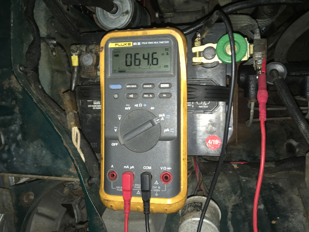
In the figure below, the above steps have been taken, and the multimeter is reading 64.6 mA (milliamps) on its sensitive setting, which is a minor parasitic draw that I’ve simulated by leaving the car’s dome light on. On a modern car with control modules, 70mA is usually considered an acceptable parasitic drain, but less than 30mA is even better.
A battery with a battery disconnect switch (green knob) installed, and the meter connected across the disconnect switch, between the battery negative terminal and ground

Note that there’s a way around all of this: You can buy what’s called a “current clamp meter,” which has a set of hinged jaws that surround the cable whose current you want to measure. It then senses the electric field inductively without your having to “splice” the meter into the circuit. These come in a few different flavors. There are clamp meters that only measure current, general purpose multimeters with integrated clamps, and clamp attachments that plug into standard meters.
Be careful, though. First, the main application for clamp meters is in household A/C wiring applications (finding how much current, for example, a refrigerator is drawing), and not all of them even measure D/C current. Second, to be useful for determining parasitic draw in a car, you need an accuracy of about 10mA (one hundredth of an amp), and you have to pay a fair amount to get a clamp meter that’s that accurate. Unless you’re a professional who does a lot of parasitic draw diagnosis, it’s probably not worth it.
Lastly, above I said that “for the most part, a circuit either works or it doesn’t.” There is a notable gray area here. In a previous installment I listed the types of circuit failures, and there was one labeled “high resistance failure.” To troubleshoot this type of failure, you need to do something called a Voltage Drop Test. Now that we’ve covered voltage, resistance, and current measurements, next week we’ll explain about voltage drop testing.
Rob Siegel has been writing the column The Hack Mechanic™ for BMW CCA Roundel Magazine for 30 years. His new book, Ran When Parked: How I Road-Tripped a Decade-Dead BMW 2002tii a Thousand Miles Back Home, and How You Can, Too, is available here on Amazon. In addition, he is the author of Memoirs of a Hack Mechanic and The Hack Mechanic™ Guide to European Automotive Electrical Systems. Both are available from Bentley Publishers and Amazon. Or you can order personally inscribed copies through Rob’s website: www.robsiegel.com.

