The laborious process of valve adjustment in a shimmed engine
A few years ago, I wrote a detailed piece about valve adjustment in a single overhead cam engine. In it, I concentrated on the common configuration, where the camshaft lobes move a set of rocker arms that see-saw on shafts and push the tops of the valve stems down. Adjustment involves measuring the clearance between the rocker and valve stem with a feeler gauge and turning a threaded stud or rotating an eccentric until the clearance is a specified amount, usually about 0.006 to 0.012 inches.
20200317172102)
But I also wrote that on vintage overhead twin cam engines, shims are often used instead, offering, “I may cover this when I [adjust the valves in] my Lotus Europa engine, as its twin-cam head uses shims.”
That time is now.
On most modern twin-cam cars, valve adjustment isn’t necessary at all because oil-fed hydraulically pressurized hydraulic lifters automatically take up the gap and remove the need for any routine adjustment. However, on many vintage cars with single and double overhead cams, along with several late-model Toyotas and many motorcycles, the cam lobes push “bucket” tappets down over the valve stems, and shims of the appropriate thicknesses are employed between the tappets and the tops of each valve stem to set the clearances. This is mechanically simpler in that it removes the need for a valve train with rocker arms and shafts, but the trade-off is that it makes valve adjustment much more complicated.
Instead of simply adjusting a threaded nut or eccentric, you need to measure the gaps between the cam lobes and the tappets, remove the cams, withdraw the tappets and the existing shims, measure the shims or read their thickness, calculate what the new shim thickness should be to set the gap correctly, procure and install those shims, then measure the clearances again to see if you got it right. (Note that the S14 engine in the BMW E30 M3 and the S54 in the E46 M3 also use valve shims, but they’re not buried under bucket tappets, and, by using a special tool, the valves can be depressed and the shims withdrawn without disassembly.)
For this reason, unlike valve adjustment in an engine with rockers, which can be a Zen-like experience that bonds you with your car, doing it in a shimmed engine is a laborious time-consuming process that no one looks forward to.
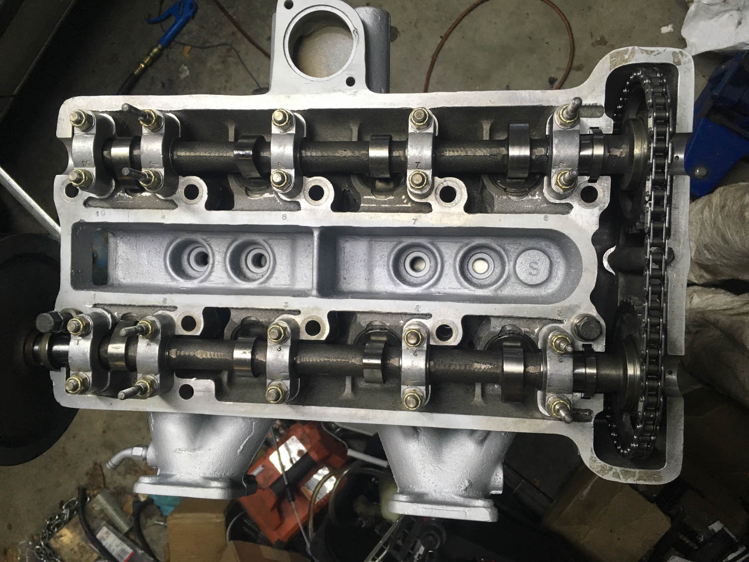
I’d rebuilt, assembled, and installed the Europa’s twin-cam engine last spring, but I’ll admit that I was actually still a valve shim newbie. I hadn’t had the experience of performing the shimming, as the machinist who performed the valve job had a ready supply of shims, so I had him do it. I did check the clearances, first on the uninstalled head where I found them in spec, and then again when the head was torqued down on the block. I found that the clearances on #1 had tightened up, but since they all were bound to change as I broke in the engine, I elected to leave them be. I put 700 miles on the engine between April and November, so when I put the car in the garage over the winter, its first post-rebuild valve adjustment and oil change were on the docket.
In any engine, the first step in valve adjustment is measurement of the existing clearances. For that, the valve cover has to come off and the engine has to be rotated to the correct position for the valves being checked. In the vintage BMWs I live and breathe, these steps are trivial: Valve covers are rarely installed with sealant, and the engine can easily be rotated either by putting the car in gear and rocking it slightly, or by putting the heel of your hand on the fan belt to tighten it and then grabbing the cooling fan and using it to rotate the engine. Then you find the position where the valves on the “companion cylinder” to the one you’re measuring are in overlapped position (the intake and exhaust rockers cover equal parts of their respective cam lobes). This ensures that, for example, on a four-cylinder engine, when #4 valves are overlapped, #1 is at TDC.
None of this, however, applied directly to the Lotus. Since it’s, you know, British, and leaks oil if you even think about lubrication within 40 feet of it, the valve cover is held on with sealant, and getting it off required a razor blade, leverage, and swearing. The car is in a very tight spot in my garage, so there’s no room to rock it to bump the valve train. And, since it’s a mid-engine car with the radiator in the front and an electric fan, there’s no fan to grab. I had to put it up on the mid-rise lift, put a ratchet on the crankshaft from underneath, and alternate between reaching under it to rotate the engine and standing on a milk crate to do the clearance measurement.
Further, it’s not like a single-cam engine, where you rotate a cylinder to TDC and measure both the intake and exhaust valve clearances in that position. The valves are angled slightly off the vertical, and to do the measurement accurately, you need to position the flat spot on the back of the cam over the valve, which means getting the cam lobes pointing upward in line with the valve stems. From a practical standpoint, this needs to be done one valve at a time. So you’re rotating the engine not four times, but eight.
The clearance measurement itself is essentially the same as a head with rockers, except that you slide the blade of a feeler gauge between the cam lobe and the tappet instead of the rocker and the top of the valve stem. Stepped or so-called “go, no-go” feeler gauges are incredibly useful for valve adjustment. For example, if the spec is .006–.008 inches, if the tip of a .006–.008 stepped feeler gauge slides into the gap but the blade stops at the step, you’ve gotten it right. Once you’ve done it for a while, for extra credit you can slide a .007-inch blade in and see if it feels better than the .006, but in general, for valves, erring a thousandth on the loose side is good practice.
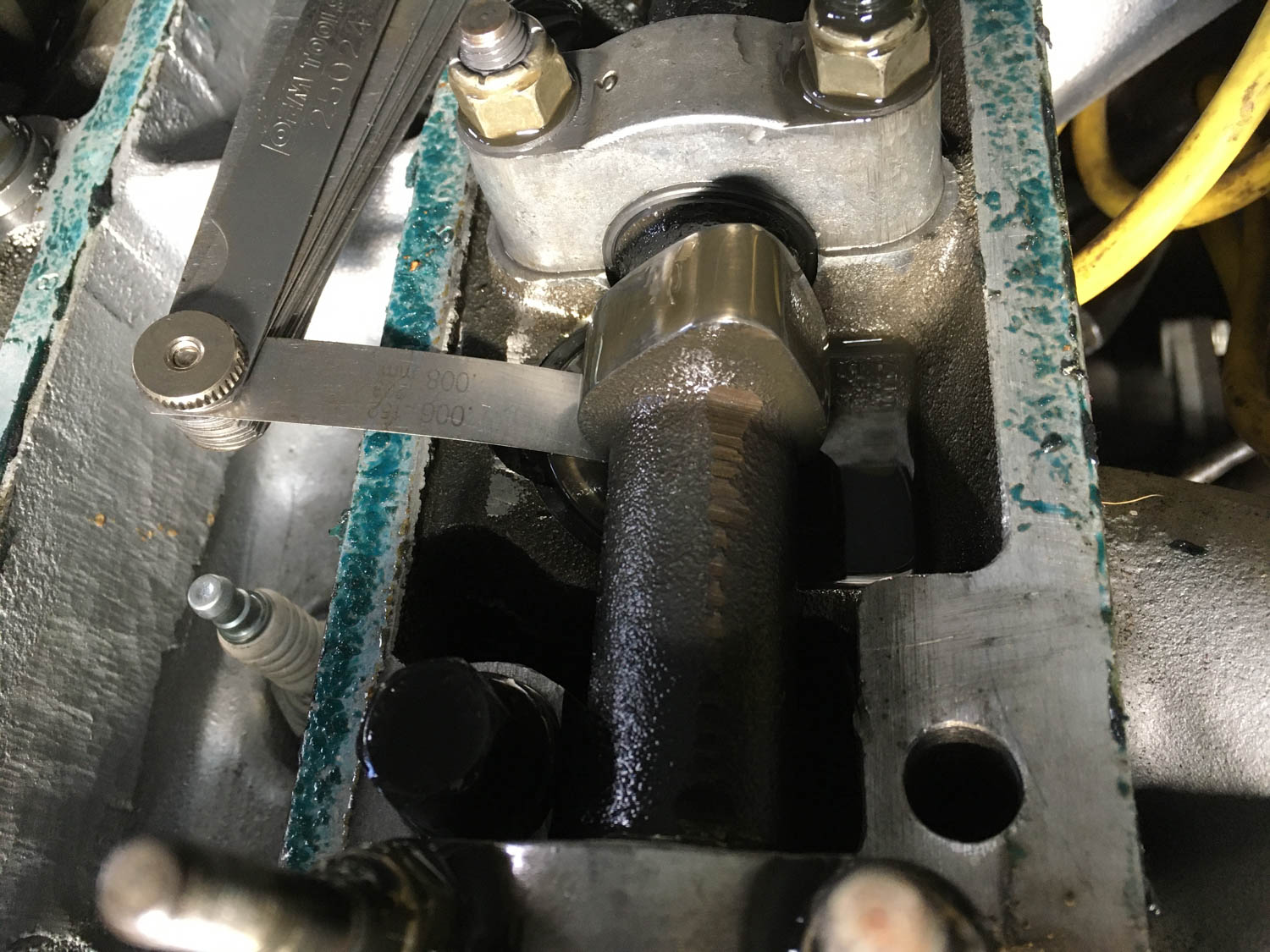
The clearances in the original shop manual called for .005–.007 inches on the intake and .006–.008 on the exhaust valves, but these days most Lotus aficionados recommend .009–.011. Neither I nor the machinist who’d assembled the head knew that, so he went by the manual, so the clearances were set tight, but again, I knew they’d change during the break-in anyway, so I left them alone.
When I measured the clearances, I found that two of the exhaust valves were .009–.011 (spot on to where I wanted them to be, thus no changes were needed to their shims), and two were .006–.800 (a little tight). Three of the intakes were at .005–.007, but #1 intake was so tight that the blade of my thinnest feeler gauge (.004–.006) wouldn’t slide into the gap. I measured a piece of paper with a micrometer at .003 inches, and it wouldn’t slide in either. I bought another set of feeler gauges with thinner blades, and to find one that went in, I had to go all the way down to the thinnest one, which was .0015. That’s one and a half thousandths of an inch, less than half the average thickness of a human hair. Yeesh. Translation: #1 intake valve was so tight that it was barely closing. I’m glad I didn’t drive the car a single mile farther.
With the clearances measured, the next step was disassembly. The valve shims are under the bucket tappets, and to remove them, both camshafts need to come out, and to do that, the timing chain has to be detached from the cam gears. Disassembly itself wasn’t the problem; it was the reassembly that concerned me.
On a Europa, the car’s mid-engine configuration makes certain things challenging. There are timing marks on the front of the cam gears. During reassembly, the block is kept at TDC, the cams are inserted at approximately the correct #1 TDC orientation, and the bearing caps are laid and tightened. Then the exhaust cam gear is inserted into the timing chain, the gear is rotated one tooth at a time until the timing mark is flush with the valve cover surface, and the gear, chain, and cam are all jiggered and juddered until the dowel pin slides into the hole while preserving the alignment. The same is then done for the intake gear. Then you insert the chain tensioner, snug things down, and verify that the block is still at TDC and both cam gear marks are still aligned as well as they can be on a 45-year-old engine whose head has been skimmed. I found this to be quite challenging when I set the cam timing with the engine on the stand. But with the engine already in the car, those cam gears are inches from the firewall, you can’t see the timing marks without a mirror, and even with a mirror, parallax prevents you from accurately assessing their alignment. I was definitely not looking forward to doing it with one hand tied behind my back.
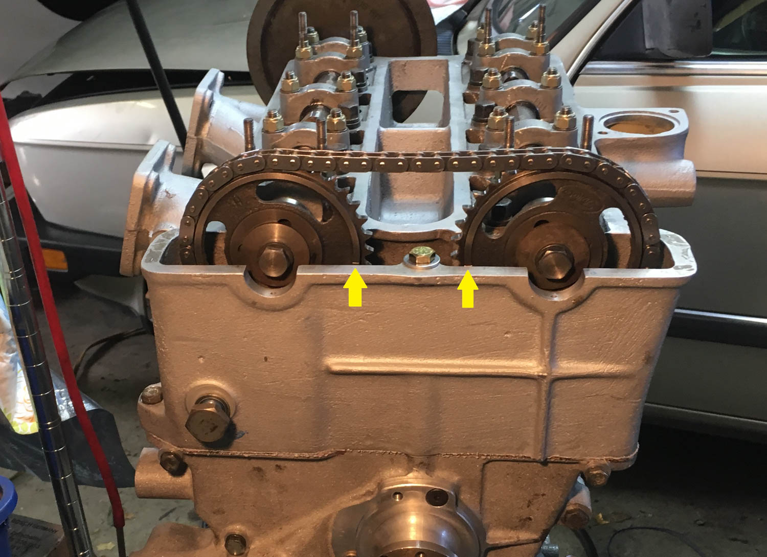
What is advised is that you mark the back face of the cams before removing them. I used Wite-Out and a straightedge on the valve cover mating surface. They’re imperfect marks, but I photographed where both intersected with the straightedge, so they should be good enough for me to know if I’m a tooth off, which is the best you can do anyway.
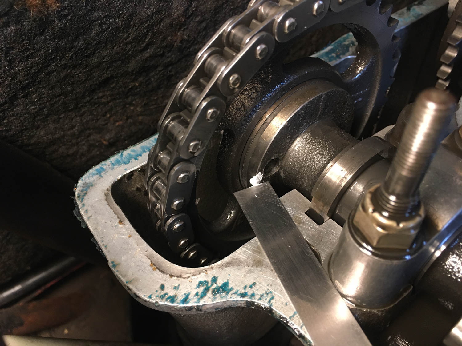
I then unbolted the cam gears (and even that is challenging given the small amount of clearance to the firewall) and suspended the timing chain using a pair of coat hangers so it wouldn’t fall down into the front of the engine and get jammed.
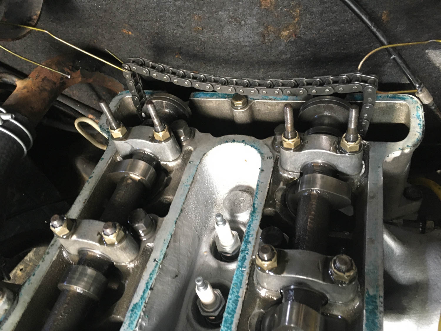
At this point, as you prepare to begin removing the camshafts, bearing caps, tappets, and shims, it is essential that all parts be organized and labeled as they are removed. The valve clearances are a function of not only the shims but the bucket tappets as well, so it’s imperative that you don’t mix them up. You can use the traditional Ziploc bags, but it’s better to use a utility box with compartments. I found a plastic box that had three columns, two of which had five rows, which was perfect because each cam has five bearing caps. While the caps themselves are stamped with the location number, the bearing shells aren’t, and they really should go back in the same place.

Finally, I unbolted the cam bearing caps and began carefully withdrawing both camshafts.
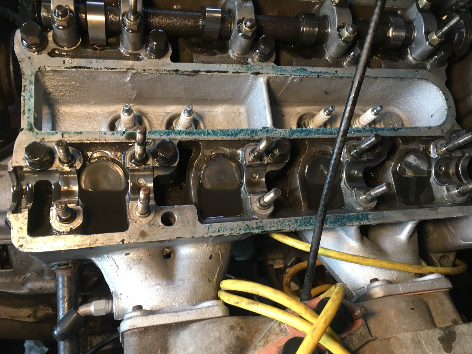
The bucket tappets can be withdrawn with either a magnet or a valve grinding suction tool. I used the latter. The valve shims are underneath. On some cars like Alfas and on many motorcycles, the shims are little inverted cups that perch like little hats on top of the valve stems, but on the Lotus and many other cars, the shims are simply dime-sized flat discs that sit inside a recess in the spring retaining cup. Typically a film of oil sticks the shim to the underside of the tappet, but if it doesn’t, you really don’t want it to fall off and drop down the engine, so it’s best to cup your hand around the bottom of the tappet as soon as you lift it out.
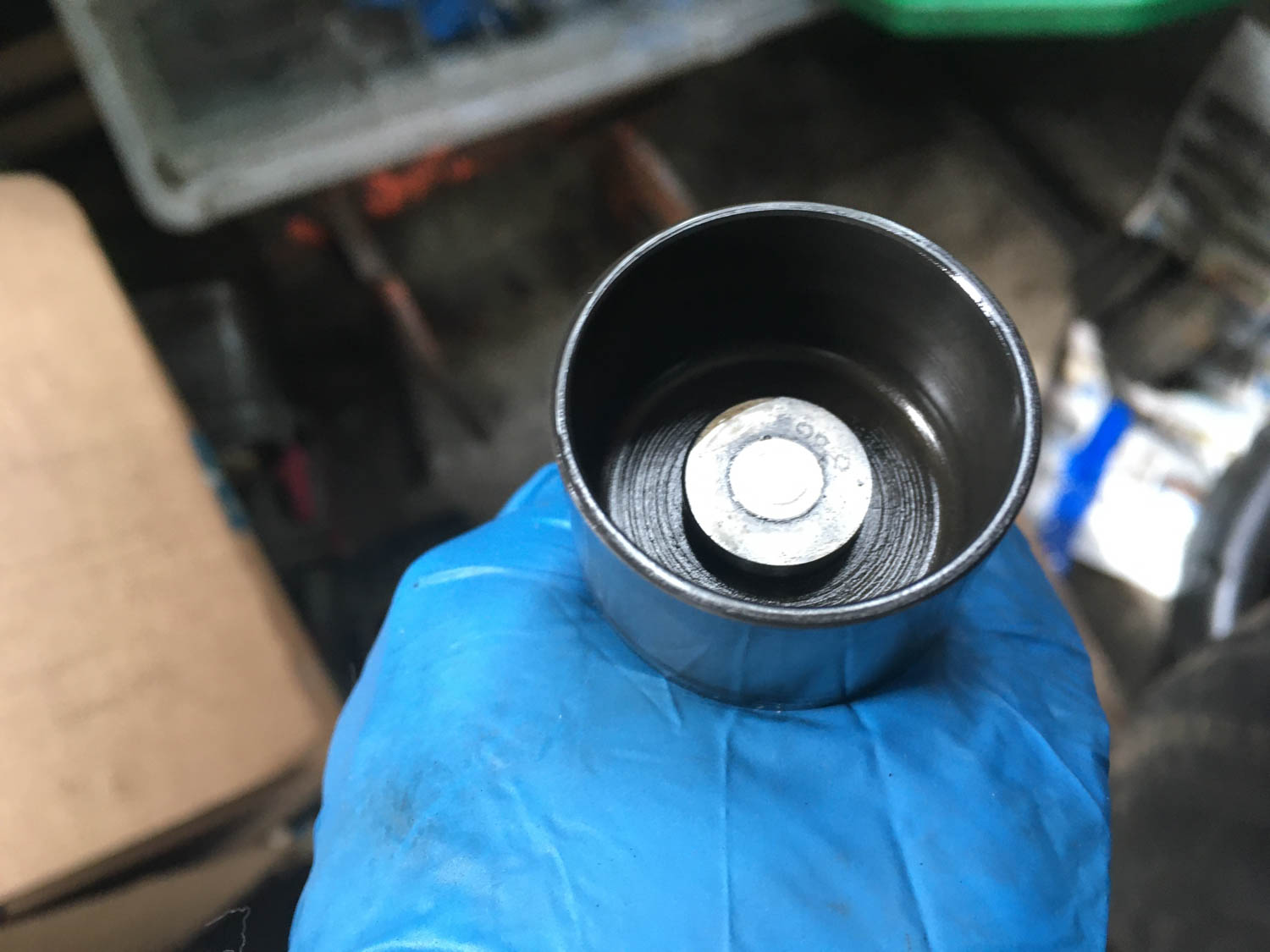
As each valve train component was withdrawn, it was immediately placed in its compartment in the plastic case.
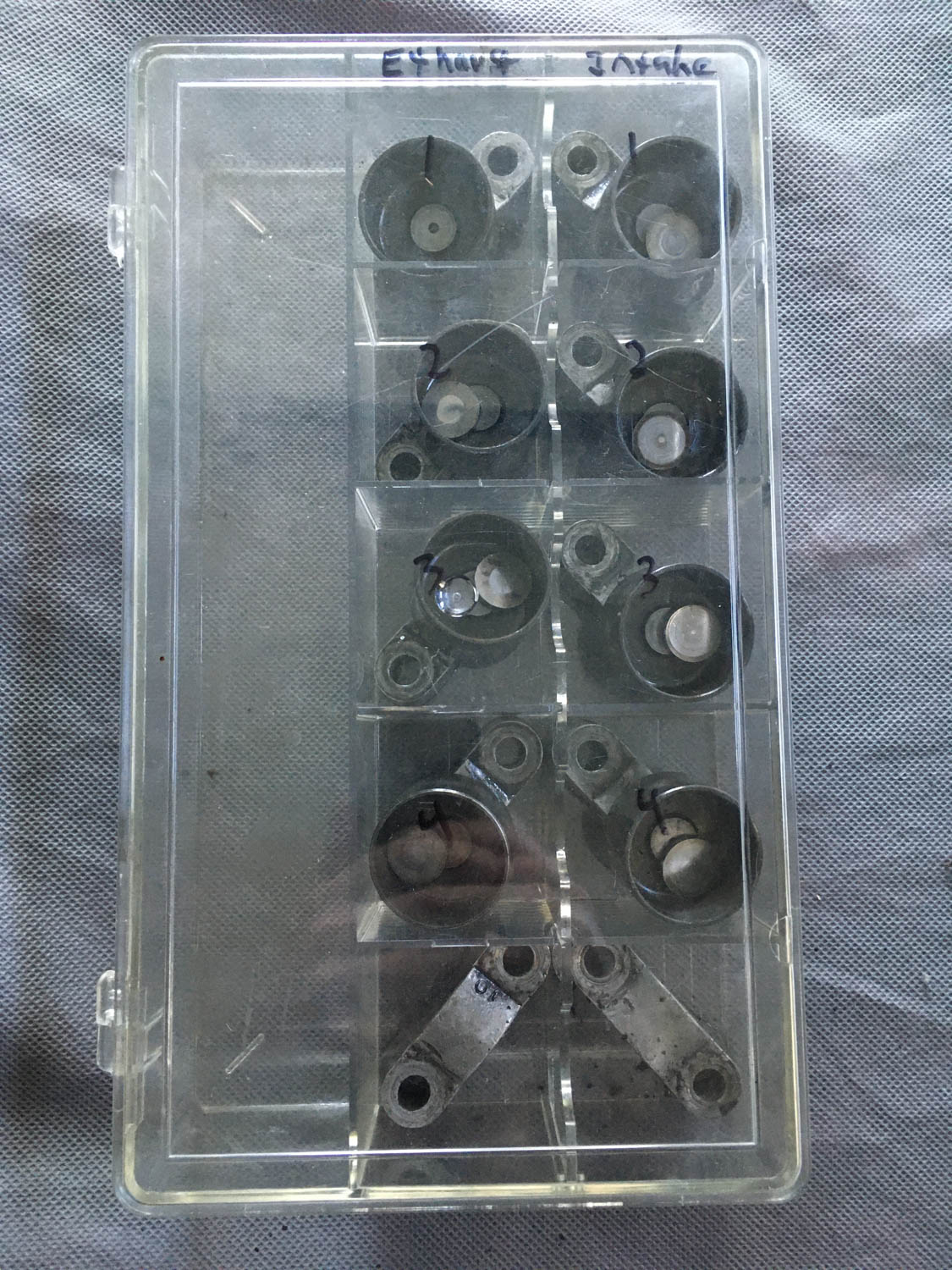
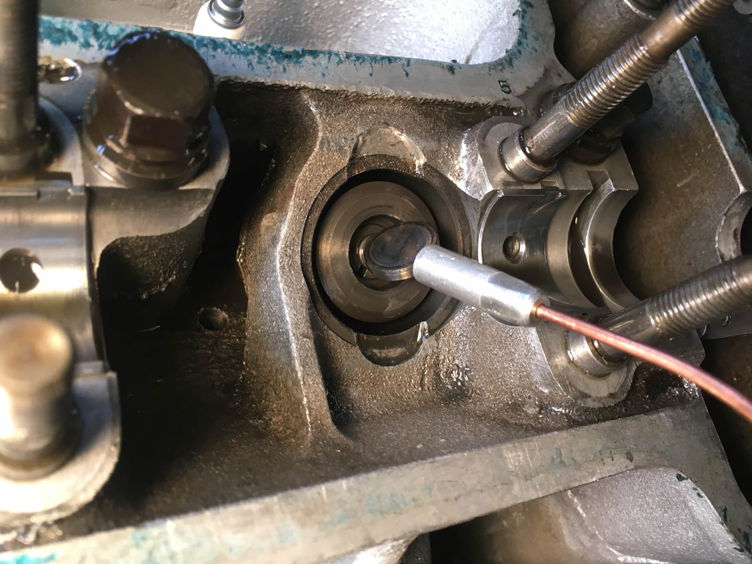
Everything went fine until I withdrew the last bucket tappet—#1 exhaust—and found the valve shim in the spring retaining cup instead of under the tappet. I put a small magnet on it, but to my surprise it stayed put. I scoured my house, found a stronger rare earth magnet, but it couldn’t pull it out either.
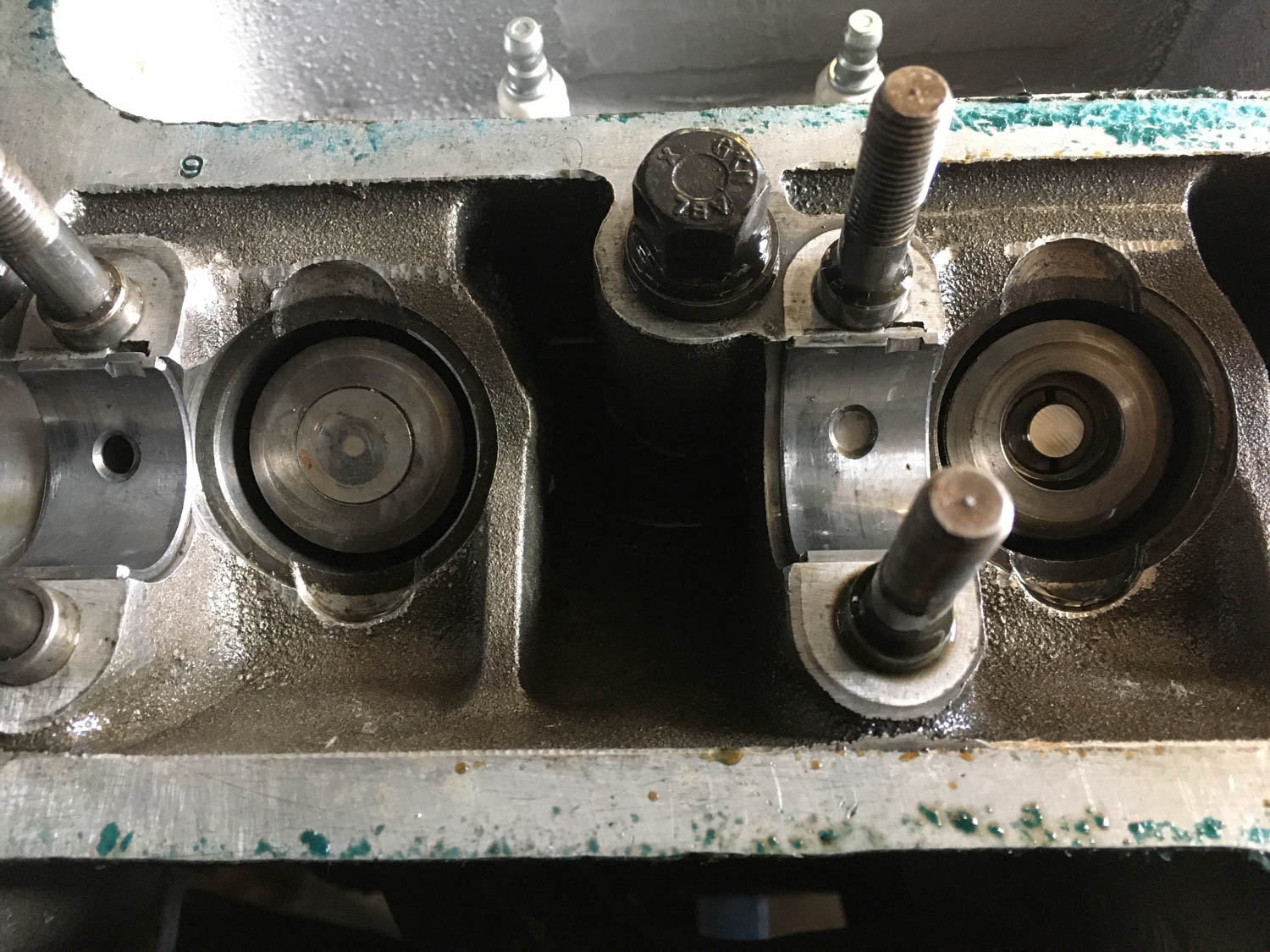
I did what I often do, which is try several things in parallel. I posted the problem to two different Lotus forums. I jumped onto Amazon and for $8 ordered a rare earth bar magnet rated at 35 pounds pulling force. I went back to the garage and looked at the stuck shim more carefully to see if there was any place where I could pry it. It was flush. There wasn’t.
But soon, a fellow named Rohan in England replied to the post I’d made on the Lotus Elan forum. He said, “The shim should only be supported at the center on the valve stem. I would try tapping the shim down gently with a flat punch on one side, and the other side should come up so you can then pry it out.” I did, and it worked perfectly; I was then able to draw the shim out with a magnet. I immediately replied to Rohan that a beverage of his choosing would be his for the taking the next time he was on my side of the Atlantic. The fact that someone a continent away immediately solved my problem is one of the best things about this car world we love.
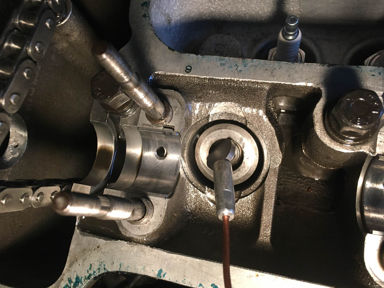
And with that, the valve train was removed, and I was no longer a valve shim newbie.
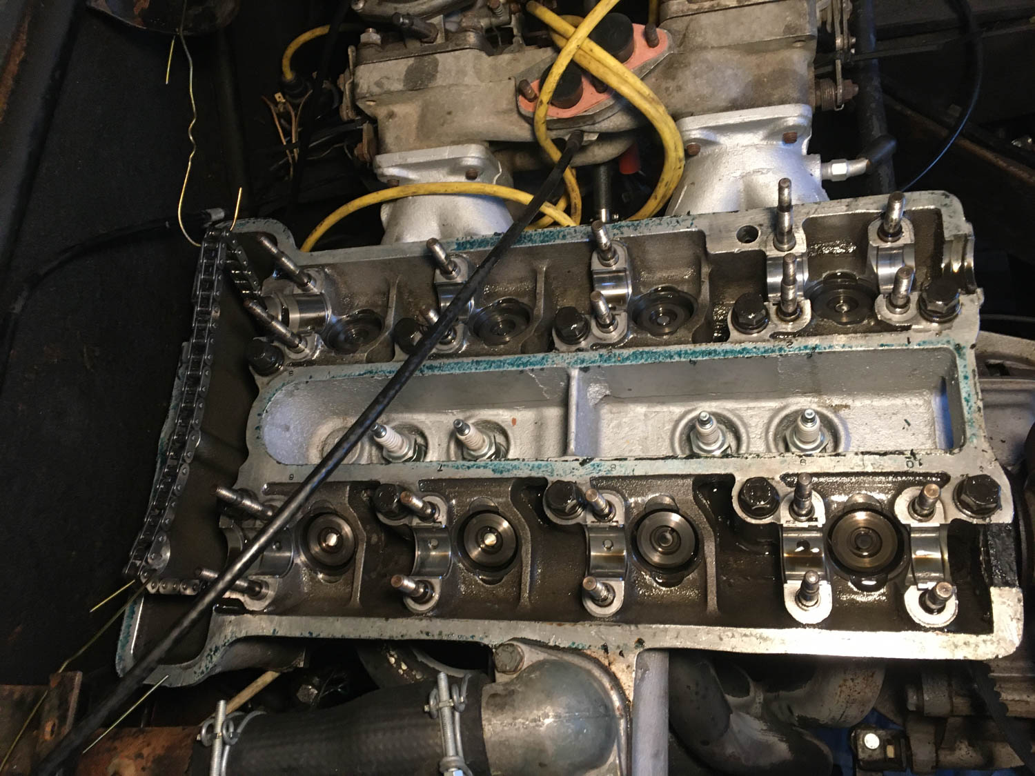
Next week, we’ll do the measuring, the calculation, and ordering of the new shims, reassembly, and that pesky cam alignment.
***
Rob Siegel has been writing the column The Hack Mechanic™ for BMW CCA Roundel magazine for 34 years and is the author of five automotive books. His new book, Resurrecting Bertha: Buying back our wedding car after 26 years in storage, is available on Amazon, as are his other books, like Ran When Parked. You can order personally inscribed copies here.
