5 types of automotive circuit failures
In this continuing series about electrical issues in vintage cars, I’d like to cover the five types of circuit failures this week.
To summarize what we detailed a few weeks ago, in order for electricity to do useful work, a circuit needs three things: a voltage source, a path for the current to flow, and a load device to offer resistance to the flow of current.
In a car, the voltage source is the battery (or, once the car is running, the alternator, with the battery acting as a filter). The path for current to flow is usually a wire connecting the positive terminal of the load device to the battery, supplying voltage, and another wire connecting the negative terminal of the load device to the body of the car to provide the ground return path.
The load device is the light bulb, the fan motor, the radio—whatever is using the electricity in the circuit.
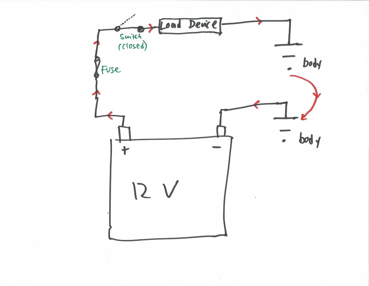
In addition, in most car circuits, there is also a fuse and a switch. Thus, in the minimum real circuit, current flows from the positive battery terminal, through the fuse, to the switch, into the load device, through a ground wire connected to the body of the car, through the body of the car, and back to the battery, like this:
A basic circuit with voltage, a load device, a fuse, a switch, and a path for current to flow.

With that in mind, let’s enumerate the five ways it can fail.
Failure Mode #1: Open Circuit
The simplest thing that can go wrong is that the circuit can be “open.” That is, it doesn’t have a closed path for the electricity to flow. If the switch is in the “off” position, that creates an open circuit, and current doesn’t flow past it, as shown below. If the fuse is blown, that also creates an open circuit.
The simplest “open” circuit is when the switch is off.

But look at the diagram. Where the black lines (the wires) go to the fuse, the switch, the load device, and the body, in every one of those spots, there is a connector, usually either a push-on spade connector or a screw-on ring terminal, and where there’s a connector, there’s the possibility of an open circuit. While it is possible for wires to break in the middle, it is far more likely for an open circuit to be caused by a connector pulling off a component, or by a wire pulling out of the back of a connector.
Failure Mode #2: Short Circuit to Ground
The second failure mode is what most people call a “short circuit,” but is technically called a short circuit to ground. As we discussed two weeks ago, in the figure below, the switch is in the open position, so no current should be flowing. We show two possible paths for a short circuit:
- If a short to ground occurs along the green path (short #1), the current will first flow through the fuse, causing the fuse to blow, opening the circuit, and stopping the flow of current before any damage is caused.
- But if the short to ground occurs along the red path (short #2)—the one before the fuse—instead, the fuse isn’t part of the circuit, and won’t protect the wiring. This is why frayed power wires touching ground cause so much damage, and can burn your ride to the ground in a minute.
Two different shorts to ground, the first protected by the fuse, the second unprotected, resulting in melted wires.

Failure Mode #3: Short Circuit to Power
In figure 4, we show two light bulbs, each with a fuse and a switch. The switch to bulb1 is closed, so current flows to it, and from there, to ground. The switch to bulb2 is open, so no current should flow to it, and the light should be out. But as we’ve drawn it, there is a short circuit going from the wire feeding 12V to bulb1 to the wire feeding 12V to bulb2. This is an example of a short circuit to power. Thus, bulb2 will turn on along with bulb1, even when bulb1’s switch is off.
What happens in a short to power.

If you imagine wires running together in old cloth-wrapped harnesses, chafing against clips and each other, rubbing off their insulation until bare wire is touching bare wire, you can see how if, for example, you hit the brakes and the fan comes on, this kind of short to power is usually the root cause.
Failure Mode #4: Component Failure
In figure 5, I’ve drawn a light bulb with a broken filament as an example of component failure. Even though there’s power, and the switch is closed, and all the wires are intact, the filament is open, so no current will flow.
“Wait a minute,” you may say. “That’s just an open circuit, but with the broken wire inside the component instead of between the components. Why are you listing it separately?”
You’re right. And if you look other places online, you won’t find “component failure” listed as a separate cause of circuit failure for this reason.
But I list it separately because when you are trouble-shooting an electrical problem in a car, you want to know if the cause is a component (e.g., a fan motor, a bulb, a switch), in which case you order a replacement and install it, or if the cause is something in the wiring, in which case you may have hours of troubleshooting ahead of you.
An example of component failure (a broken filament inside a bulb).

Failure Mode #5: High Resistance Failure
When we talked about Ohm’s Law two weeks ago, I said that resistance is a good thing, that if a circuit doesn’t contain a load device to offer resistance to the flow of current, you have a short circuit that’ll melt wires. That’s true, but there’s a difference between the intended resistance in a load device, and the unintended resistance created by corrosion.
The Greek symbol Omega (Ω) is used to represent resistance. In the figure below, we depict that resistance is present at every connection in a circuit. If this kind of unintended resistance is too high, it saps voltage, and makes it so the current reaching the circuit’s load device isn’t enough for it to do its job. A light might come on, but flicker and then go out. A motor might groan and turn for an instant, then stop.
In a later installment, we’ll cover the subject of Voltage Drop Testing, which is how you use a multimeter to detect a high resistance failure. For now, though, just park the thought that a high-resistance failure is a non-binary circuit failure. That is, the circuit might not be open, but also might not be closed enough to allow enough current to flow.
Resistance is present at every connection.

There. That was actually quite a bit. Next week, we’ll cover the basics of how to use a multimeter to help detect these kinds of circuit failures.
Rob Siegel has been writing the column The Hack Mechanic™ for BMW CCA Roundel Magazine for 30 years. His new book, Ran When Parked: How I Road-Tripped a Decade-Dead BMW 2002tii a Thousand Miles Back Home, and How You Can, Too, is available here on Amazon. In addition, he is the author of Memoirs of a Hack Mechanic and The Hack Mechanic™ Guide to European Automotive Electrical Systems. Both are available from Bentley Publishers and Amazon. Or you can order personally inscribed copies through Rob’s website: www.robsiegel.com.


Really enjoyed your article on 5 types of auto circuit failures. I found your article while searching for and explanation with examples of circuit feedback. In school I use a 1996 for Mercury Cougar without autolamps.
The headlamps are using a single dual element bulb. I create an open circuit on the left low beam that is powered when low beam lights switched on. “Symptom or customer concern I tell the student is one low beam is BRIGHTER than the opposite side.” When they turn on the high beams the fault switches from left to right head lamp. It is a feedback like I’m sure you’ve seen on taillights also and especially on trailer lighting.
Really great article not just for older vehicles, but anything electrical on wheels from 1900-2024 and beyond. My only feedback that is not positive is only 1 of 7 diagrams could be viewed.
If I unplugged the camshaft sensor and someone started the car would the computer think that was a open circuit