How to spot a Ford pushrod V-8, from flathead to 460
Let’s say it’s your lucky day, and you’ve found an engine laying around in the back of a garage with an unknown history. Or maybe you’re trying to discern which engine was swapped into a car, and all of the aftermarket parts between the fenders are muddying the waters. In any case, the first step is always to identify the engine.
Determining precisely which engine you’re looking at under the hood can be difficult. Heck, sometimes a brand produced more engine families in the same decade than you can count on both hands. If you’re pretty sure you’re looking at a Ford V-8, the following guide will help you make the proper ID of your engine so that you can dive deeper into the ID.
This article, focusing on Ford passenger car V-8s, isn’t a full history on engine tech or applications. It’s intended as a primer to help you narrow things down and, in turn, enrich your gearhead knowledge. We’ll focus on the biggest visual keys to look for when you come face-to-valve-cover with eight cylinders of Detroit metal.
Ford flathead V-8: 1932–53
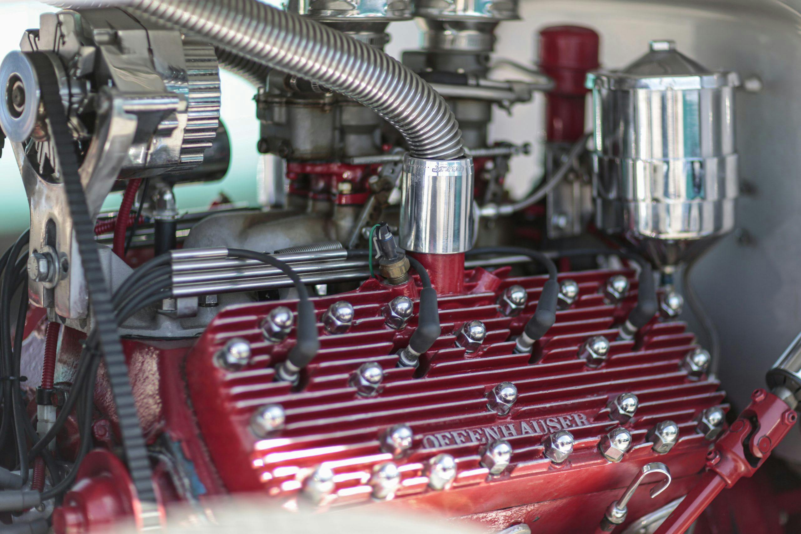
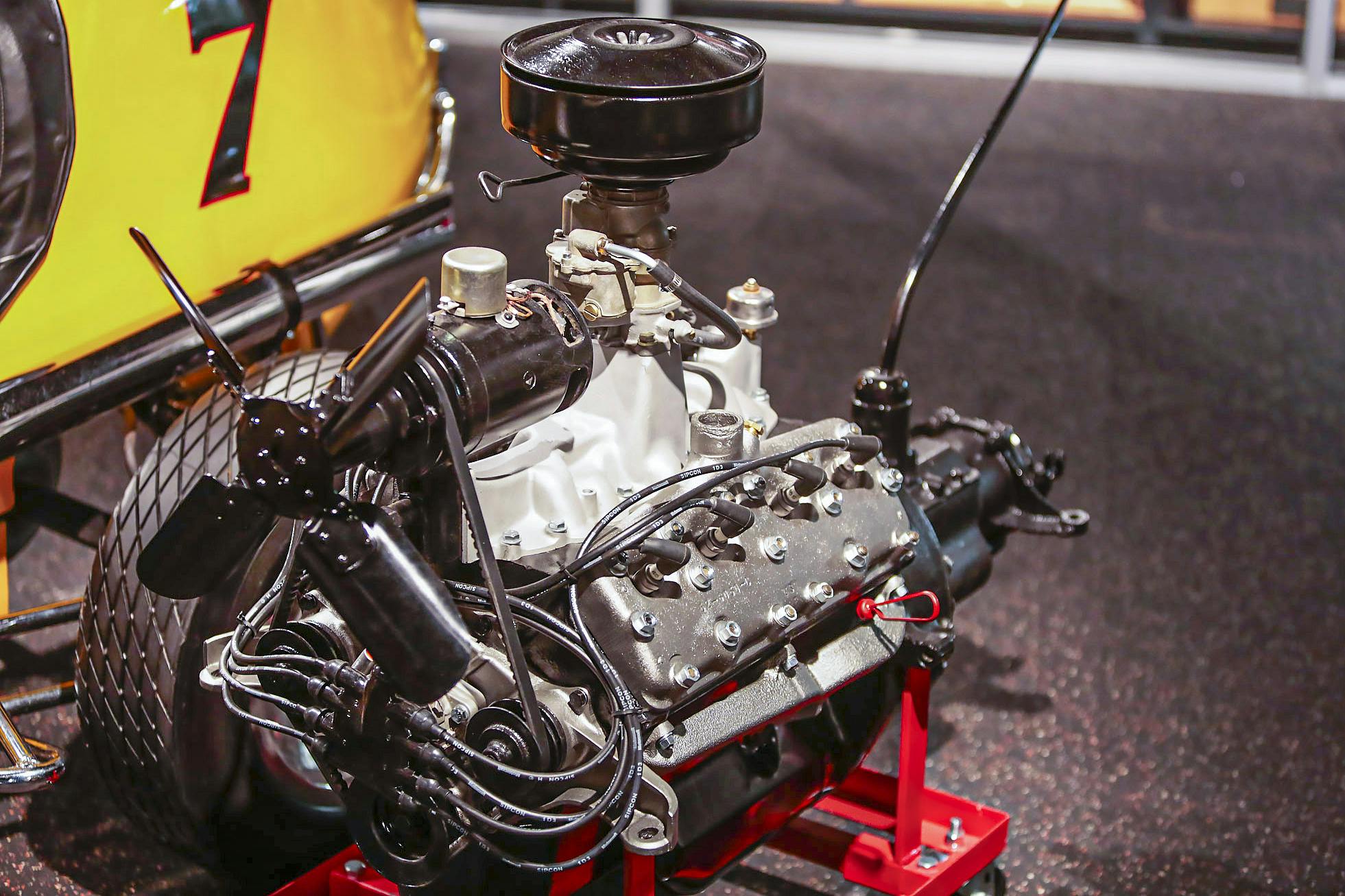
OK, so technically it’s not a pushrod, as the valves live where pushrods would be, but we kind of had to include them because this is the engine that practically gave birth to hot-rodding. Lucky for us, factory flatheads are easy to spot. They’ll have plainly visible spark plugs mounted through the top of the cylinder head. Aftermarket heads make it more tricky, as they may use twin plugs per cylinder or even switch to overhead-valve operation.
Factory displacements: 221 cubic inches, 239 CID, and 255 CID. The V-8 60 was 135 CID and a less-common truck variant at 337 CID made its way into some Lincolns.
Distributor location: In front of the timing set. Various designs were used that can help narrow down the exact year, but they were all mounted in the same basic location.
Exhaust port layout: Only three exhaust ports exit the block on each side, spaced 0—0—0
Intake port layout: Located in the lifter valley of the block, they’re grouped in pairs, spaced 00—00
Valve cover bolt pattern: No valve covers! However, 1932–1937 flatheads use 21 head studs, 1938 and on use 24 head studs. The smaller 60-hp flathead introduced in 1937, known as the V-8 60, uses 17 studs.
Lincoln Y-block V-8: 1952–63
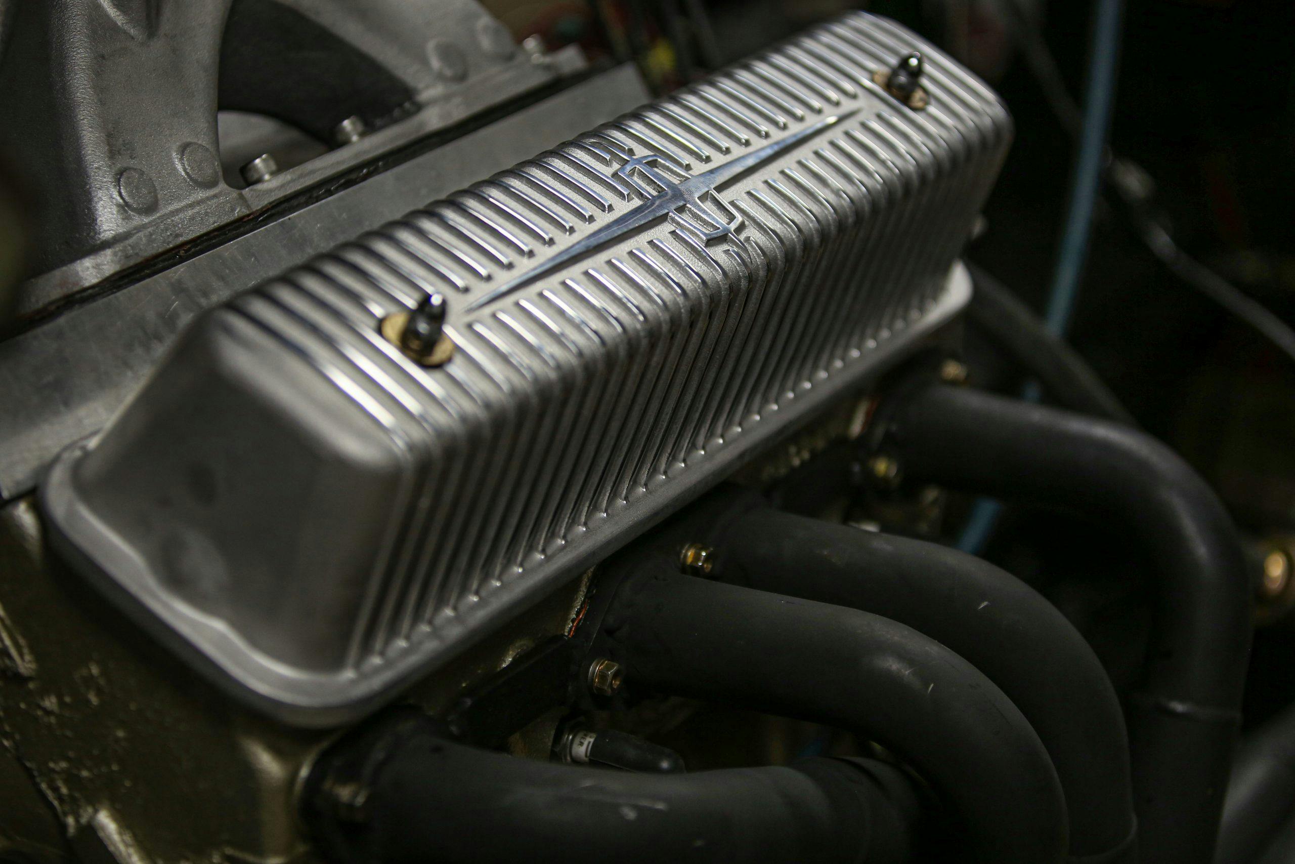
Lincoln cars ditched the 337 flathead in 1952, and as a result enjoyed much more power thanks to the improved breathing capability of the Y-block’s new OHV design. With 4.63-inch bore spacing, this is a medium-sized V-8 that was never developed for large displacements.
Factory displacements: 317 CID, 341 CID, and 368 CID engines were used in Lincoln cars, 279 CID, 302 CID, and 332 CID were used in Ford’s heavy-duty trucks.
Distributor location: Rear, canted to the passenger side.
Exhaust port layout: Spaced 0—00—0
Intake port layout: Spaced 00—00
Valve cover bolt pattern: Two bolts per cover, one in the center near each end.
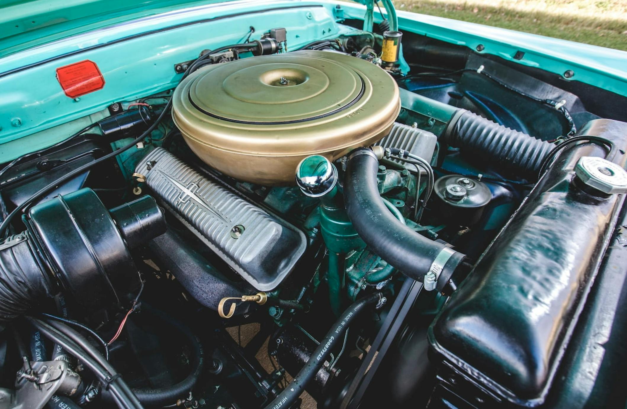
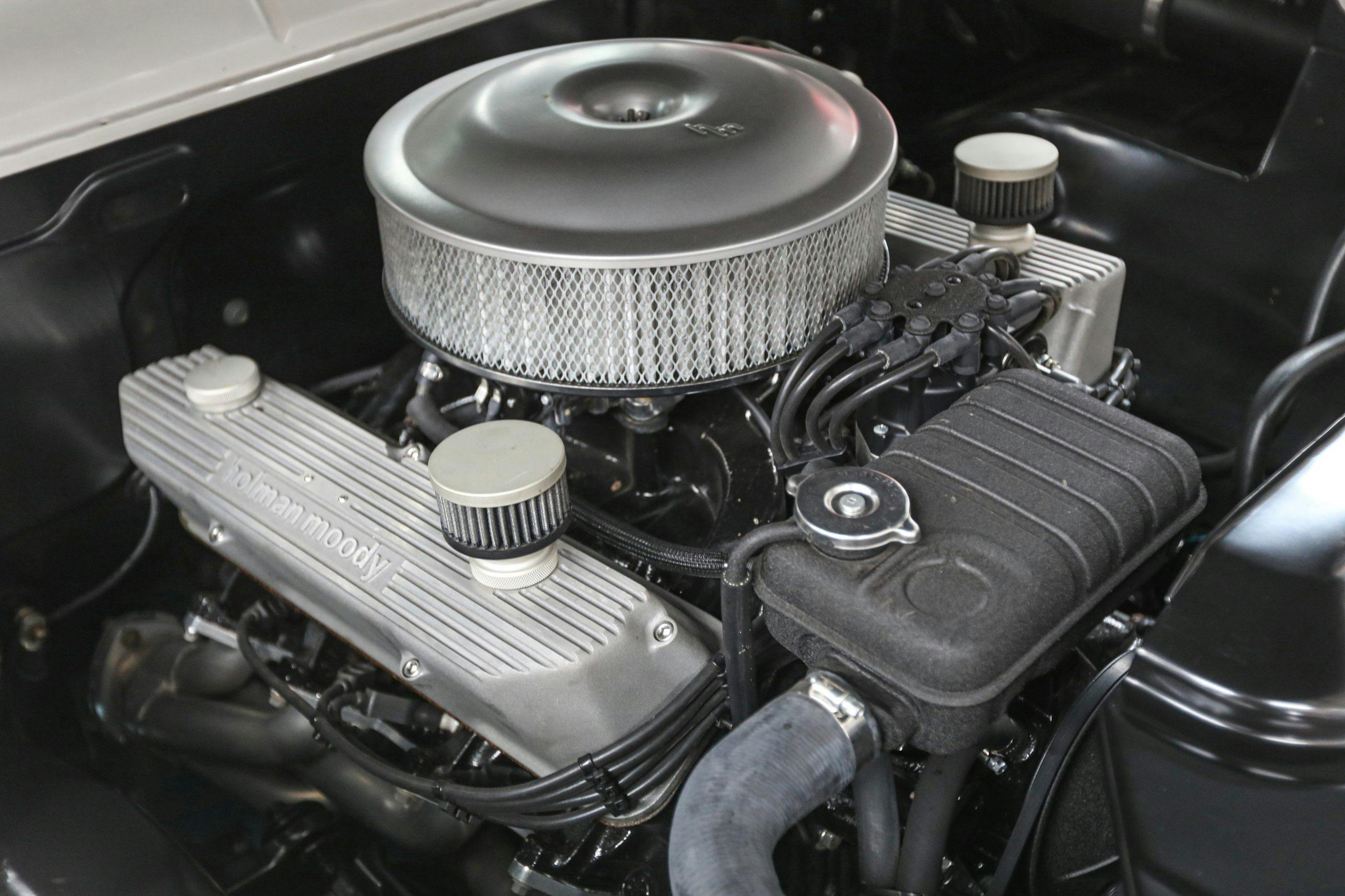
Ford Y-block V-8: 1954–64
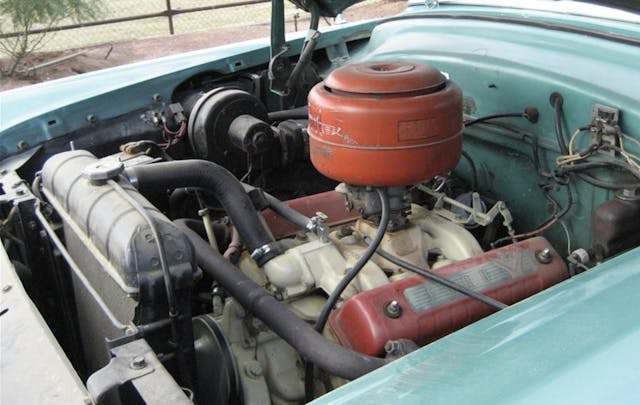
Ford’s main flathead replacement debuted with the 1954 models and brought OHV performance to its mainstream cars. While the valve covers and exhaust ports looked like those of the earlier Lincolns, Ford’s version of the Y-block used a 4.375-inch bore spacing that fell within the typical range of small-blocks.
Factory displacements: 238 CID, 256 CID, 292 CID, and 312 CID.
Distributor location: Rear, canted to the passenger side.
Exhaust port layout: Spaced 0—00—0.
Intake port layout: Spaced 8—8. (Intake ports are stacked on top of each other, in pairs, making the Ford engine relatively easy to spot.)
Valve cover bolt pattern: Two bolts per cover, one in the center near each end.
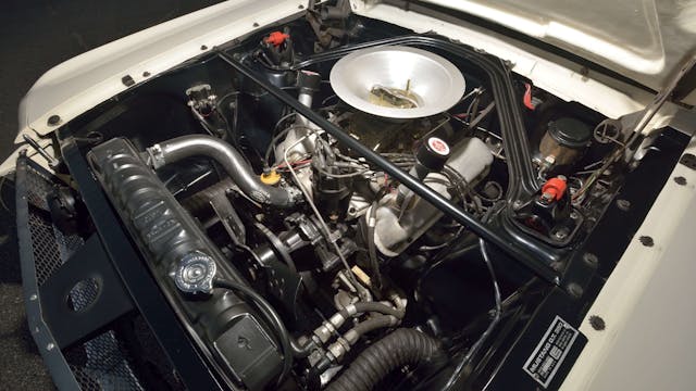
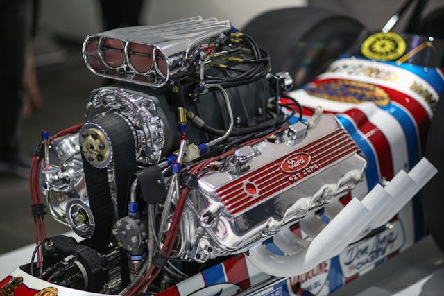
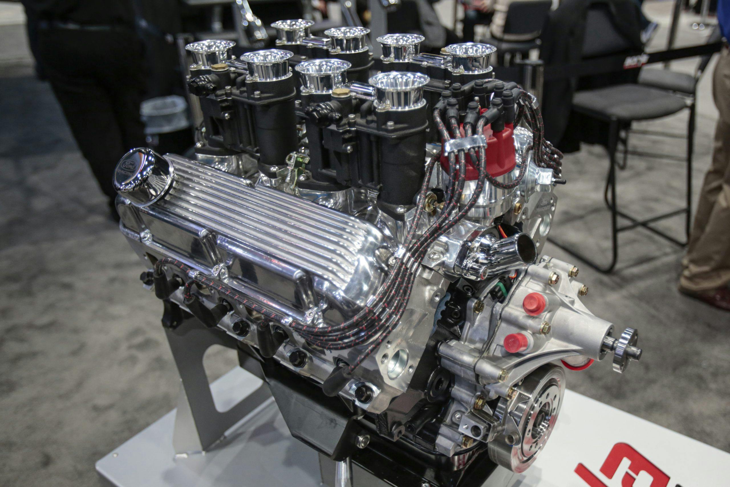
Ford FE V-8: 1958–76
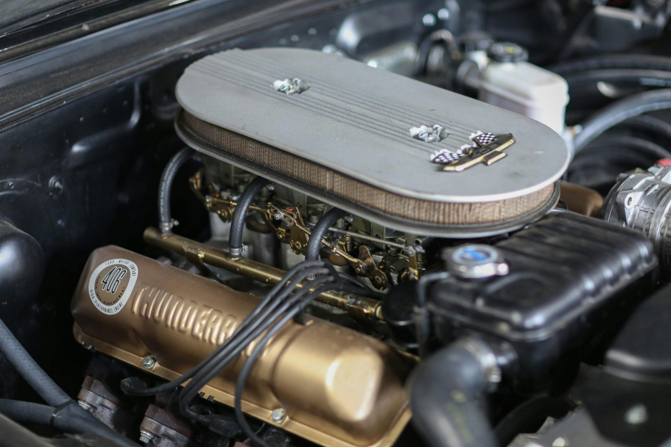
Like the Windsor that would soon follow, the FE engine could be found in everything from bare-bones trucks to drag racers—even the Shelby Cobra. Not really a big-block, the FE is more of a medium-sized engine, like an AMC or Pontiac V-8, allowing for a wide range in displacement.
Factory displacements: 332 CID, 352 CID, 360 CID, 361 CID, 390 CID, 406 CID, 410 CID, 427 CID, and 428 CID.
Distributor location: Front, straight up, slightly offset to the driver side.
Exhaust port layout: Spaced 0-0—0-0. The mirrored valve arrangement, with the two middle intake valves near each other, causes the distance between the center two exhaust ports to be a bit wider.
Intake port layout: Spaced 0-0-0-0. Rare tunnel-port heads used an intake port layout that placed the inside ports closer together.
Valve cover bolt pattern: Two on the outboard side, three on the inboard side.
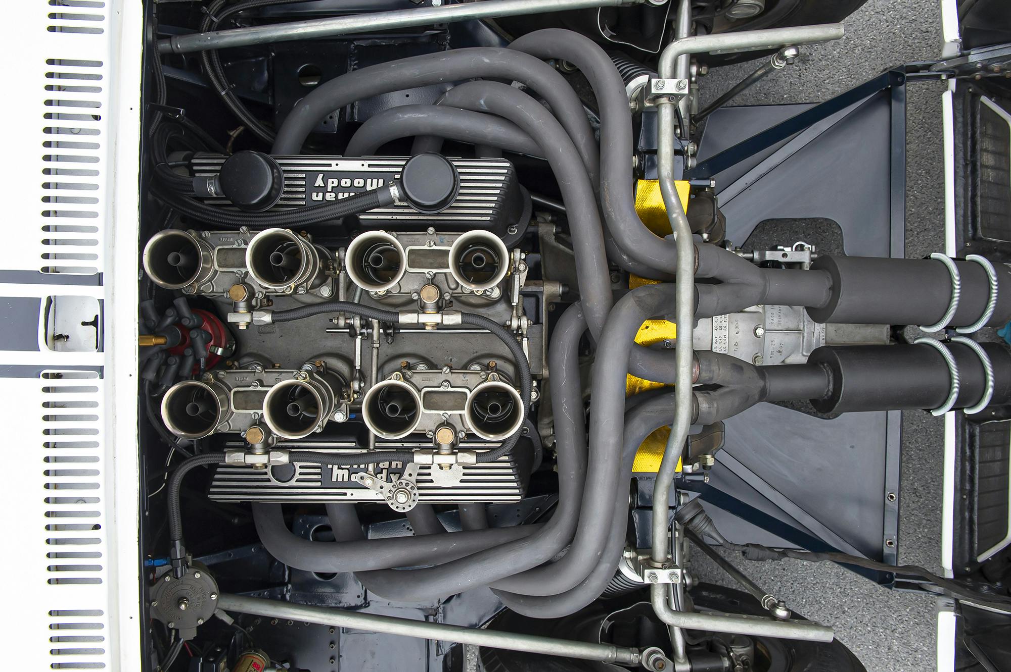
Noteworthy examples: The FE also spawned the SOHC 427 “Cammer.”
MEL (Mercury-Edsel-Lincoln) V-8: 1958–67
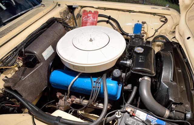
The MEL V-8 engine is a true big-block, with a 4.9-inch bore spacing to fit huge pistons. These engines were used in heavy cars and bear some mechanical similarities to the smaller FE, but without the FE’s mirrored valve arrangement.
Factory displacements: 383 CID, 410 CID, 430 CID, 462 CID.
Distributor location: Front, straight up, slightly offset to the driver side.
Exhaust port layout: Evenly spaced, 0-0-0-0.
Intake port layout: Evenly spaced, 0-0-0-0.
Valve cover bolt pattern: Three on the outboard side, three on the inboard side, with the inboard side featuring wider spacing. It looks a bit like a big Windsor, but the factory stamped valve covers are more rectangular in shape.
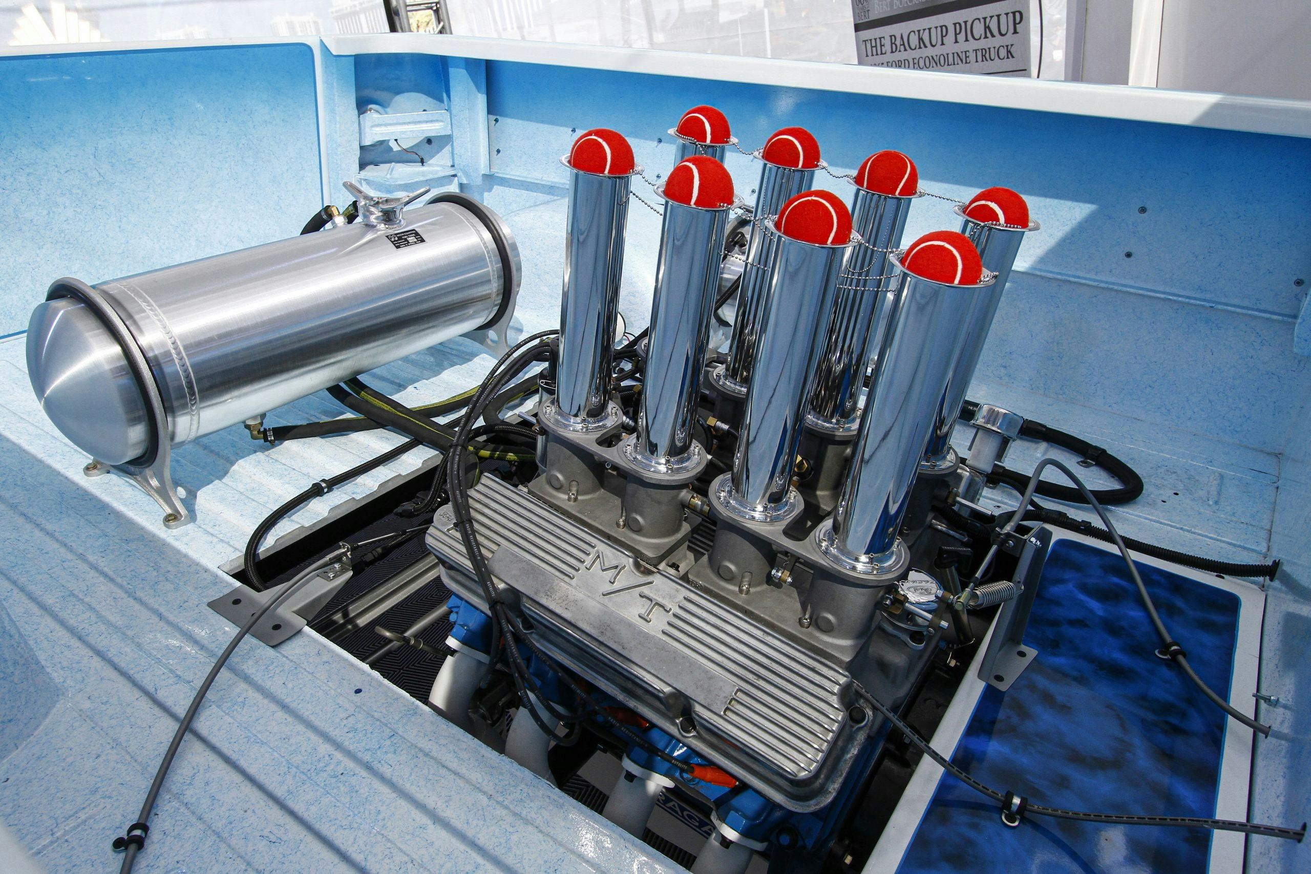
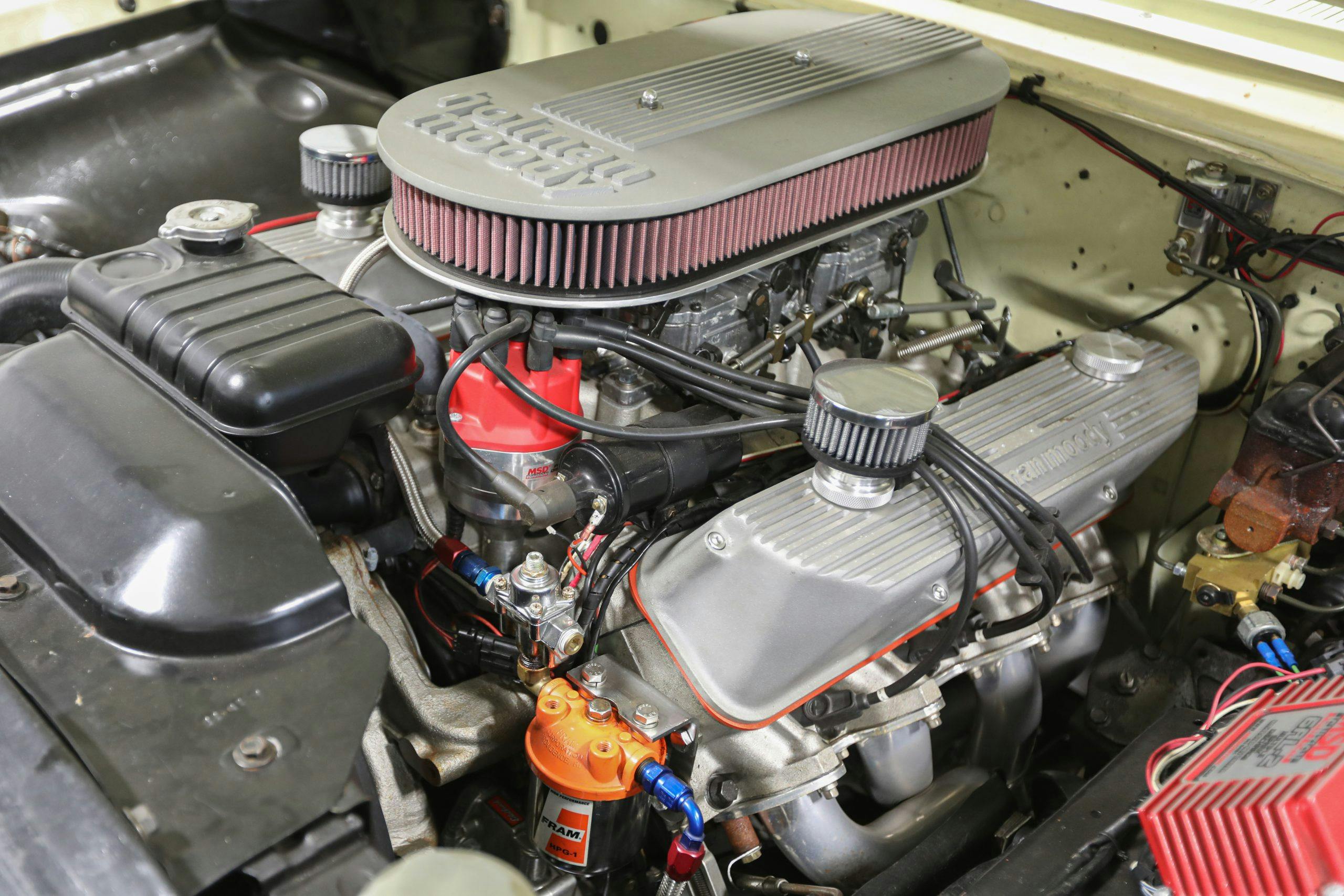
Ford Windsor V-8: 1961–2001
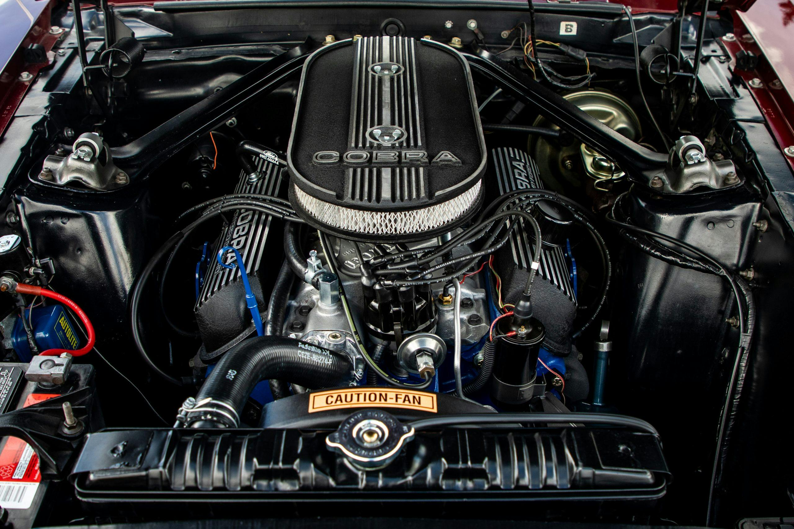
Ford’s compact engine, known for its trapezoidal valve covers. These brutes were used in just about everything from GT40s and Cobras to pickups.
Factory displacements: 221 CID, 255 CID, 260 CID, 289 CID, 302 CID, and 351 CID.
Distributor location: Front, straight up, slightly offset to the driver side.
Exhaust port layout: Evenly spaced, 0-0-0-0.
Intake port layout: Evenly spaced, 0-0-0-0.
Valve cover bolt pattern: Three on the outboard side, three on the inboard side, with the inboard side featuring wider spacing. Exceptions: Boss 302. See 335 Series below.
Further identifiable features: The thermostat housing bolts to a vertical boss (protuberance) at the front of the intake manifold.
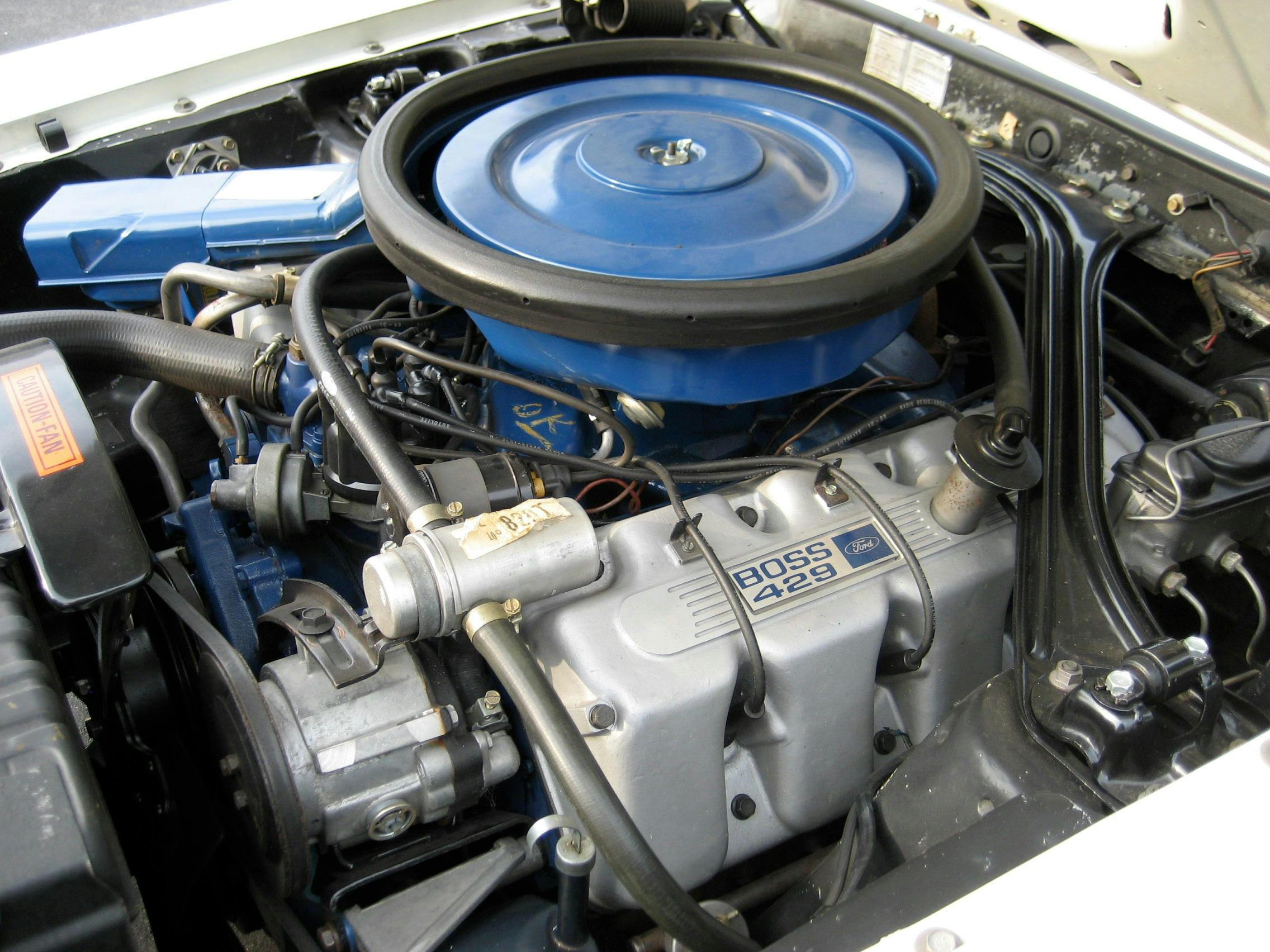
385-series Ford V-8 1968–98
These burly big-blocks have a sizable aftermarket and can be built into brutal drag racing engines or workhorse stump-pullers.
Factory displacements: 370 CID, 429 CID, and 460 CID.
Distributor location: Front, straight up, slightly offset to the driver side.
Exhaust port layout: Evenly spaced, 0-0-0-0.
Intake port layout: Evenly spaced, 0-0-0-0.
Valve cover bolt pattern: Four on the outboard side, three on the inboard side. Some aftermarket valve covers, including those from Ford Racing, omit the center inboard bolt hole.
Notable variants: This engine family gave birth to the Hemi-fighting Boss 429, which is easily recognized by unique valve covers that have indentations for the spark plugs.
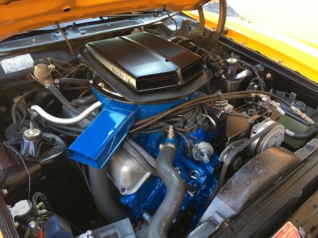
Ford 335-series: 1970-1974 (C), 1975–1982 (M)

Things get a little tricky with the 335 engine family. There was the 351C V-8 (for the Cleveland, Ohio, plant where they were cast), plus 351M and 400M variants. The 351C is a short-lived powerhouse that features a deck height of 9.206 inches—one inch taller than the 260, 289, and 302 Windsor—and just a bit shy of the 351 Windsor’s 9.480 and 9.503 respective deck heights for ’69–’70 and ’71–’96. It uses a small-block bellhousing pattern.
An even taller-deck version with similar architecture (measuring 10.297 inches) was used for the 351M and 400M, both of which contained larger, 3.0-inch main bearing journals. Both of the “M” engines use the same big-block bellhousing pattern as the 385-series V-8s—appropriate given their use in light trucks.
Factory displacements: 302 CID (Australia only), 351 CID, 400 CID.
Distributor location: Front, straight up, slightly offset to the driver side.
Exhaust port layout: Evenly spaced, 0-0-0-0.
Intake port layout: Evenly spaced, 0-0-0-0.
Valve cover bolt pattern: Four on the outboard side, four on the inboard side. This pattern was also used on Boss 302 for 1969 and 1970, as it’s basically what you see on early Cleveland heads.
Further identifiable features: The thermostat housing bolts to a horizontal boss on the front of the block. Aside from the bellhousing pattern, the 351M and 400M can be distinguished from the 351C via their taller deck height and resulting wider intake manifolds.
Still stumped with your mystery pushrod Ford V-8? Post photos in the comments below and let the Hagerty Community take a swing at the ID.

