The laborious DIY process of valve adjustment in a shimmed engine, Part 2
Last week, we talked about the basic steps to adjust valves in an engine that uses shims under bucket tappets. To summarize, those steps are:
- With the engine dead cold, carefully measure the valve clearances with feeler gauges, and record them in a table.
- Rotate the engine to top dead center (TDC) and remove the camshafts.
- Remove the bucket tappets and valve shims, putting them into a labeled organizing container so you’re absolutely certain which one goes where.
- Measure the thicknesses of the valve shims and record their sizes in the table.
- Calculate the size valve shims you need to obtain the desired clearances and order them.
- Reinstall the bucket tappets and camshafts.
- Measure the resulting clearances to see if you got it right.
A little more involved than changing spark plugs, right?

Because the procedure is a pain, you want to do it as accurately as possible to maximize your chances of getting it right. The accuracy of the shimming is a combination of the accuracy of the clearance measurement, the shim measurement, and the precision of the manufacturing of the new shims. When performing the clearance measurement, you use feeler gauges, and thus you’re only going to get it accurate to the thickness difference between the different blades, which is one-thousandth of an inch. You don’t have control over the manufacturing of the new shims, but you do have some control over the accuracy of their measurement. You can measure them with calipers, which is good to about a thousandth. However, if you use a good micrometer, you can get the accuracy closer to a few ten-thousandths.
 and the marks on the handle give you thousandths of an inch, but the Vernier scale (yellow arrow) allows you to measure shim thickness to a few ten-thousandths of an inch.")
Now, it might seem like hubris to think that you can actually shim the valves to a ten-thousandth when the go/no-go feeler gauges are only getting you to within one thousandth. You can’t. But there are two reasons why you should use a high-quality micrometer to measure both the original and the new shims.
The first is that the Vernier scale of a good micrometer is simply more accurate than the dial gauge on a set of calipers and should be able to get you if not to the ten-thousandth, at least sub-thousandth. The downside is that an analog micrometer takes a little getting used to. It typically has a sleeve scale and a Vernier scale. The sleeve scale (white arrow above) is the set of marks that are uncovered as you open the micrometer. On mine, the sleeve scale has four markings every tenth of an inch, making each of them 25 thousandths. There are then 25 markings on the rotary scale on the handle, giving you the number of thousands since the last mark on the sleeve scale.
So, if the mic was opened just past the first sleeve mark (.025), and the rotary scale reads 10, the measurement would be .025 + .010 = .035 inches. Most of the shims I’m measuring are just under or just over a tenth of an inch. In the photo above, it’s just over a tenth, so the thickness is 0.1 plus the reading on the rotary scale, which is just under eight thousandths, so you have to call it seven, plus the number of ten-thousandths you read off the Vernier scale. If the reading is just under a tenth of an inch, you have to remember that the thousandths on the rotating handle are to be counted from the nearest mark on the sleeve scale, which is 0.075, and then add the reading on the rotary scale. It takes some practice, but it is considerably more accurate than calipers, where it can be difficult to tell a thousandth apart on the dial.
But the second reason that a micrometer is better than calipers is that calipers will only measure the thickness across the high points on the faces of the shim, whereas a mic will allow you to directly measure the spot in the center where the valve stem pounds on the underside of the shim and often creates a small recess there, and that’s the area affecting the actual valve clearances.


But the real issue is that you want to get all the measurements as accurate as you can because you want to target the new shims to put the clearances at the middle to upper end of the range, not the lower end of the range. This is because valves tend to close up over time. You’d think they’d loosen as the shims get little valleys battered into them, but the other dynamic is valve seat recession, where the pounding of the valves against the seats in the head pulls them deeper, raising the tips of the valve stems and decreasing clearance. By measuring accurately, you can help ensure that the sums of all these measurement errors don’t result in the valves being too tight. For example, if the exhaust valve clearance spec is .009 to .011 inches, you generally want to aim for 0.10 to .011, not .009.
If you read up on shimmed valve adjustment, you’ll see that, to calculate the thickness of the shim you need, the formula is:
New shim = measured clearance – target clearance + existing shim
So, if the measured valve clearance is .007 inches, the target clearance is .010, and the existing shim is .110, you need a shim that’s .107.
Now, I don’t like that formula because it doesn’t really tell you what’s going on. I like to use an extra step that calculates the delta (the difference between the measured and target clearances) and do it all in Excel and build a table that does the calculation for me. The table looks like this:
|
|
|
exhaust target |
0.01 |
|
|
|
valve |
clearance |
middle |
delta |
old shim |
new shim |
|
#1 |
.006 to .008 |
0.007 |
-0.003 |
0.110 |
0.107 |
|
#2 |
.009 to .011 |
0.010 |
0 |
0.105 |
0.105 |
|
#3 |
.009 to .011 |
0.010 |
0 |
0.100 |
0.100 |
|
#4 |
.007 to .009 |
0.008 |
-0.002 |
0.09 |
0.088 |
The top row says that this table is for the exhaust valves and that the target clearance is .010 inches, right in the middle of the desired range. The “clearance” column is the measured clearances obtained with the stepped go/no-go feeler gauges. The “middle” column is obviously the number in the middle of that range. If you use a stepped gauge, you know that the clearance isn’t the top number because you’ve checked that the feeler gauge blade won’t go in past the step. That is, if you used a .006–.008 blade and it stops at the step, the clearance is either .006 or .007. After you’ve done valve adjustments for a while, you learn how to tell the difference between the two by feel, but otherwise you just assume it’s the middle value.
The “delta” column is the difference between the middle measured clearance and the target clearance. It’s the number that tells you how far off you are. Negative means the valve is too tight; positive means too loose. So, here, #1 is too tight by three thousandths, #2 and #3 are right on and require no change in shims, and #4 is too tight by two thousandths. If it were .002 instead of -.002, it would mean the valve was too loose by two thousandths.
The reason I like to do it this way is that, when you see the delta number, you can know which way the shim needs to go. For example, with #1, the delta is negative by three thousandths. This means the valve is too tight, so it needs a thinner shim to allow for more clearance, so the replacement shim has to have a thickness that’s smaller than the existing one, smaller by an amount equal to the delta of three thousandths. The old shim was .110, so the new shim needs to be three thousandths less, or .107. When you do it this way, you’re less likely to make mistakes, both because the calculation is performed automatically by Excel, but also because you can see explicitly how being under or over clearance translates into needing thinner and thicker shims respectively. Make sense?
And, with that, I carefully transcribed the valve clearances and shim thicknesses into Excel and built my tables. Since I had two exhaust valves that measured with stepped feeler gauges perfectly at the spec of .009 to .011, and because that spec is already pretty generous, I left the target clearance at the center spec value (.010) and calculated and the shim thicknesses needed to bring the two other valves to .010. For the intake valves, though, because the .005 to .007 spec is much tighter, I aimed at the high side of the spec (.007) and calculated the thicknesses for three needed shims. I put the five shims on order.
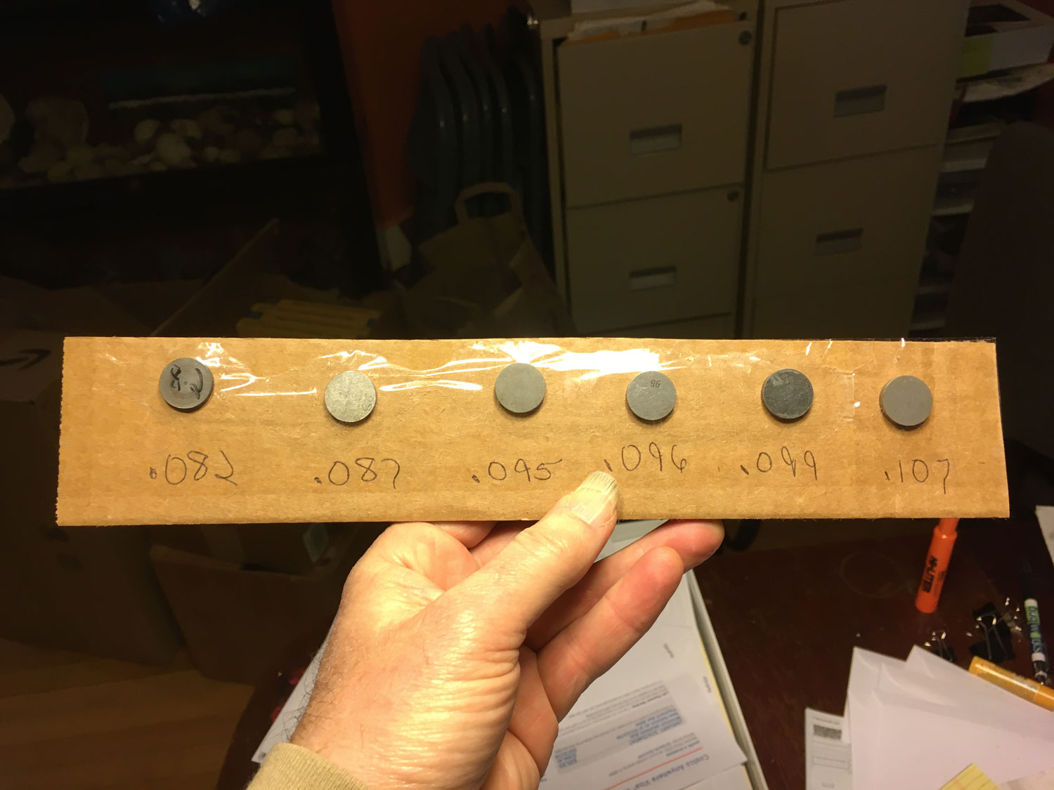
A few days later, the shims arrived. The ones I’d bought were labeled in one of three different ways. Some had the thickness etched into the surface, some had it printed, and some simply were written on with a Sharpie. The vendor was considerate and taped them down with the thickness written beneath each shim.

Regardless of the labels, though, as I’ve explained, it’s important to confirm their thicknesses with the micrometer, and in doing so, I found a problem. The .107 shim I’d ordered for one of the exhaust valves was .1077, enough that it was likely to tip the clearance from the middle or end of the .009 to .011 bracket to the beginning. Even though it meant waiting a few days, I ordered another .107 shim and a .106 as well and asked the vendor to mic them to be certain.
Note that, once you have accurate measurements for the old and new shims, you can calculate what the final estimated clearance should be. It’s similar to the formula above, but there we were calculating the thickness of the new shim, whereas here we’re using that thickness and back-calculating the expected clearance. The formula is:
New clearance = old shim – new shim + measured clearance
So, if the old shim was .104 inches, the new shim is .101 inches, and the measured clearance was .007, the estimated new clearance should be .104 – .101 + .007, or .010. Again, it’s good to think of this spatially to sanity-check it: The new shim is .003 thinner than the old, so the new clearance should be .003 larger than the old.
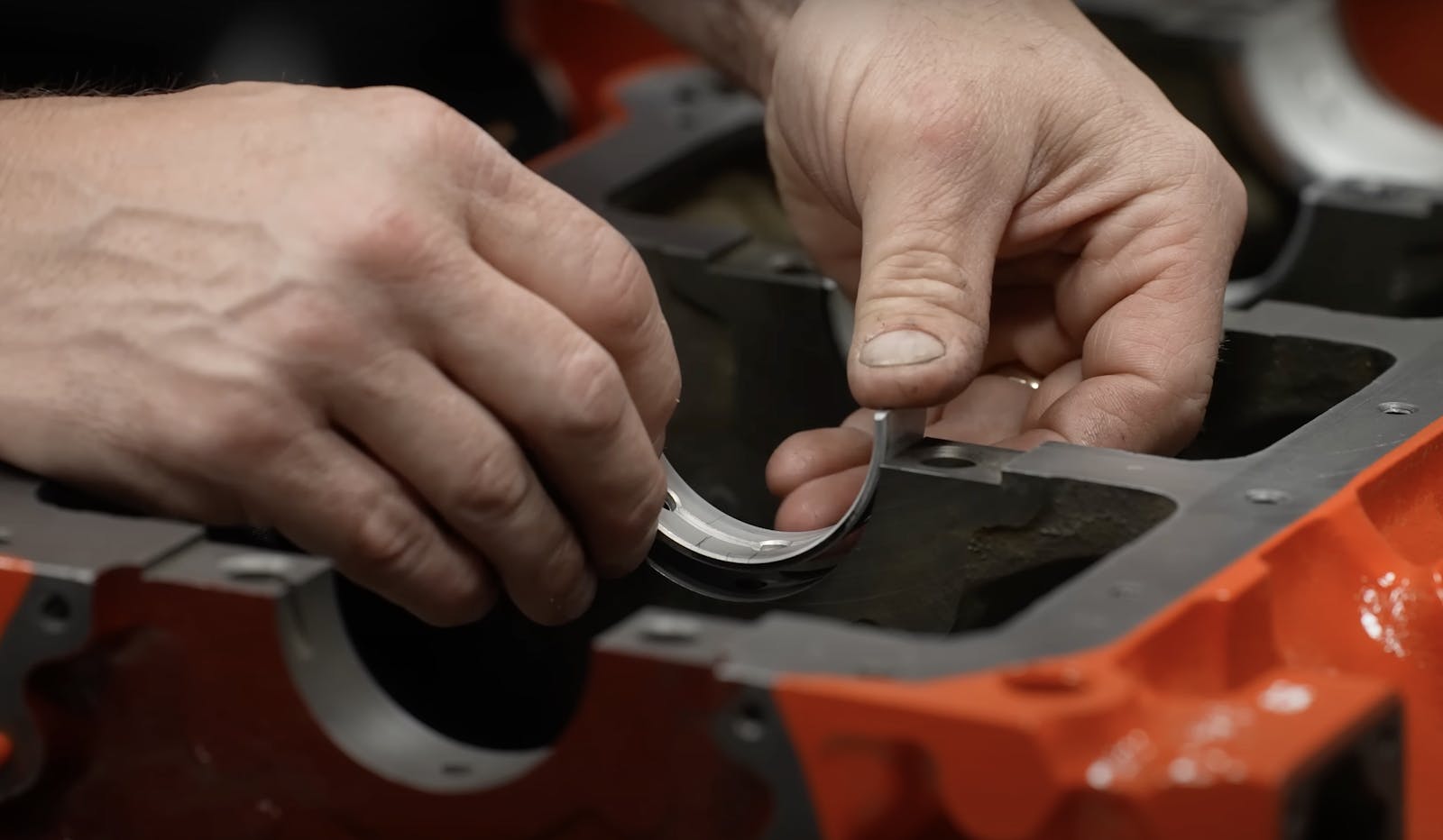
Finally, with the new shims plus the organized box of the old shims and other valve train components I’d removed, I very carefully selected and placed the correct shim on top of each valve stem, double-checking against my original hand-written table of what I’d removed, mic-ing the shim before placing it whether it was the original shim or not, and verifying the whole common-sense “valve was three thou tight, new shim is three thou thinner than the original shim, so we’re good” thing. I then cleaned each of the bucket tappets with a rag, smeared a coating of oil on the outside, and placed them over their original valve stems. Note that it’s really important that the bucket tappets go back in their original locations, since the valve clearances are affected not only by the different shims but also by differences in thickness in the tops of the bucket tappets.
One surprise was that there was a wide variation in the diameter of the valve shims. Most of the original shims were about 0.62 inches and had a little wiggle room inside their retaining cups, but as I said last week, one was so snug that it was difficult to withdraw. The new shims I ordered were all closer to .625. One of them was .628, which made it only fit into the cup if I pushed on it and it snapped in. I methodically rotated its edge on a fine file until it could be easily inserted and withdrawn from its cup.
I’d hoped to say, “And then I installed the cams, measured the clearances, and everything worked perfectly,” but unfortunately I forgot that the nyloc nuts holding down the cam bearing caps really should be single-use, and I’d neglected to put them on order. So, until next week…
***
Rob Siegel has been writing the column The Hack Mechanic™ for BMW CCA Roundel magazine for 34 years and is the author of five automotive books. His new book, Resurrecting Bertha: Buying back our wedding car after 26 years in storage, is available on Amazon, as are his other books, like Ran When Parked. You can order personally inscribed copies here.