Once upon a timing chain: Clearance issues aren’t always very clear
When last we left the troublesome reassembly of the twin-cam motor for my 1974 Lotus Europa, I’d spent a month trying to fit the custom inner and outer timing covers needed to receive the new cartridge-style water pump. This is a desirable modification that allows you to change the water pump without having to pull the motor and yank the head, but the pace was glacial due to the need to test-fit everything before assembly.
This is necessary for several reasons. First, even when fitting bone-stock components, both the head and the front timing covers mount to the block without dowels or locating pins, so you need to test-fit to check for proper alignment. Second, the use of new components such as the Dave Bean Engineering cartridge-style water pump kit and its inner and outer covers introduces new variables into the mix.
Last month, Bean sent me a revised outer cover that fixed a clearance issue with the timing chain. However, when I continued the test-fitting, I discovered additional issues that fell into a murky gray area between what I could reasonably expect of an aftermarket part (even an expensive one from a reputable Lotus parts house) and what’s simply the lay of the land with these motors.
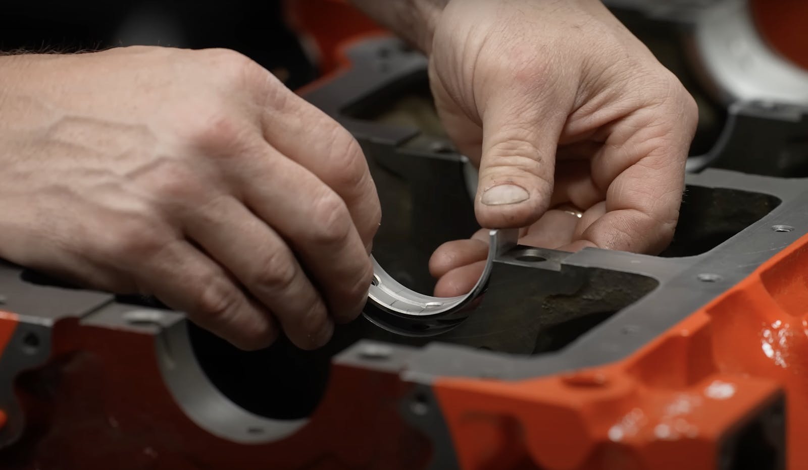
During test-fitting, in addition to checking for timing chain clearance, you look for proper alignment of the top and bottom surfaces of the inner and outer covers with each other as well as with the oil pan surface at the bottom of the block and the clearance to the block deck at the top. You also need to make sure that the holes in the inner and outer covers that receive the cylindrical cartridge-style water pump are concentric, that all bolt holes line up, and that the front of the crankshaft is centered in the seal. Obviously, since the covers are rigid, these are not independent variables, so you need to fix one of them and check the others against it. I initially held the covers together, turned them upside down, leveled their tops on a flat surface, and checked that the bottom surfaces and the bolt holes lined up. They did, except for one errant bolt hole for the alternator bracket which I widened into compliance with a circular file.
There’s a cork gasket that goes between the front of the head and the upper surface of the timing covers, so the covers need to sit slightly below the block deck surface to allow the gasket enough room. My block had been decked slightly to clean up a little surface damage, so this clearance was smaller than it should’ve been. For this reason, the way that I was approaching test-fitting was to fit the inner cover—also called the backplate—and force it all the way down on its mounting bolt (remember, there are no locating pins or dowels). I found that, when I did this, the bottom surface of the backplate aligned almost perfectly with the oil sump surface at the bottom of the block. I then test-fit the outer cover and found that by forcing it up on its mounting bolts, I could align both the upper and lower surfaces with the backplate to within a few thousandths of an inch. I was pleased.


The only problem was that, when I tried to insert the cartridge water pump, it felt like something was preventing the o-rings from sliding in as easily as I would’ve expected. So I tried it a different way. I pulled off the covers and test-fit the water pump through both on the bench. This forced the water pump holes in both covers to be concentric. The pump fit fine, but I found, to my surprise, that the upper and lower surfaces of the covers were no longer level with each other—the outer cover was shifted down from the inner one by about 0.016 inches at both top and bottom.

Further, I found that, when I tried to fit the covers this way to the block, the inner cover was too high. It was almost flush with the block deck. This allowed very little room for the cork gasket. With careful measurement, I determined that the cork gasket would need to compress beyond 50 percent of its thickness. I found references online to the cork gasket squishing out of place when compressed too far and causing oil leaks.
At this point, I did what I’ve done several times before. I sought the expertise of the gentleman I refer to as The Lotus Engine God (TLEG)—Bill McCurdy at Williams Racing in Harvard, Massachusetts. I brought him the covers and pump, showed him the misalignment of the upper and lower surfaces, and explained about the lack of clearance for the cork gasket. He recommended that we address both issues with one pass of the milling machine—that we take a total of 0.025 inches off the top to mill the surfaces flush and create some room for the cork gasket. (The video can be seen below.)
Unfortunately, the bottom surfaces couldn’t easily be milled flush like the top surfaces, due to the semicircular relief in the outer cover for the front crankshaft seal. I was concerned that the 0.016-inch step was outside the 0.010-inch spec, but Bill said that the cork oil pan gasket should accommodate it, and a little extra RTV at the step should seal it up. I used a flat file to bevel the step so it wouldn’t be so abrupt.

I brought everything home, test-fit yet again, and began to prepare for actual assembly. Unfortunately, I’d bought the gasket set 5½ years ago, and discovered that the thin paper gasket that sits between the backplate and the block had curled and dried up like a leaf in November. I sourced another one from RD Enterprises, one of the two U.S.-based Lotus parts suppliers (Dave Bean being the other).

When the new gasket arrived, I found that it was noticeably thicker than the original paper one, more like shirt cardboard, but I didn’t think too much of it; gaskets get updated all the time.
I prepared to test-fit the head on the block. Since there are no locating pins, the advice is to take a threaded rod, cut two pieces that, when threaded into a head bolt hole, sit about 3/4-inch proud of the deck, smooth the edges so they won’t scratch the underside of the head, and cut screwdriver slots in them. This way, you can use them to guide and seat the head, and then, once a few head bolts are in, unscrew them and withdraw them with a magnet.

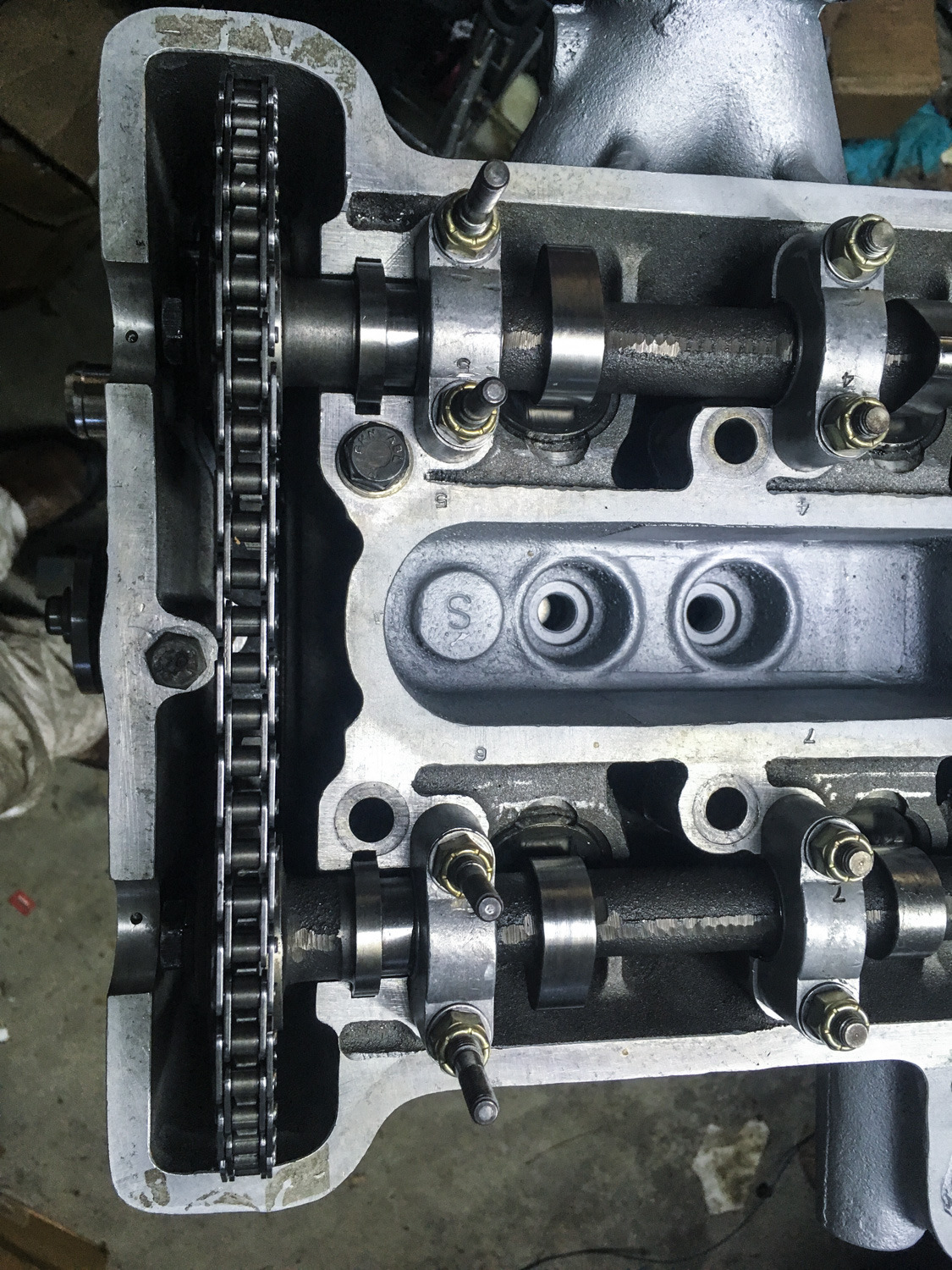
I test-fit the covers, timing chain, tensioner, head, head gasket, cork gasket, and cam gears. The clearance between the back of the chain and the inner surface of the timing chest seemed tight, but I found that if I shoved the head as far forward as it would go on its bolts (again, no locating pins) it seemed adequate.

One minor problem showed up: After test-fitting everything, rotating the engine about ten times, and disassembling, I noticed a wear mark on the inside of the outer timing cover. It was due to the front of the jackshaft gear rubbing against it. The point of contact was the back side of the hollow passage feeding the water pump, so I wanted to be very careful before I ground anything off. I spoke with Ken Gray at Dave Bean. He told me that the casting at that point was a quarter-inch thick, so a little light grinding should be fine.

With that, at long last, I set about mounting the covers for real. However, once all the bolts were in, including those attaching the head to the front cover, I found that there was very little play; the idea that I could pull the head forward to gain clearance for the timing chain was a misnomer. With everything snugged down, I fit the cam gears and timing chain. Where the chain passed around the crank gear, there was enough clearance, but at the top, I was alarmed to find that it appeared that the chain was hitting the front of the inside surface of the head. The chain was so close that it was scraping the still-curing RTV off the front of the cork gasket.


I was mortified. How had I screwed this up? What had I missed? I posted the problem to the Lotus Elan forum (since all Elans have twin-cam engines, that forum tends to be deeper on twin-cam knowledge than the Europa forum), then walked away from it for the evening. That night, I slept badly, my dreams peppered with clearance-related images.
The intelligence from the Elan forum was that, if the cams and their gears were stock, and if the crank and jackshaft were mounted with their correct thrust washers and locating plates (respectively) in the block, the gears should be in alignment with each other. Visually, this appeared to be the case. Because the timing chain appeared close to the head as it came down from both cam gears, it was unlikely that the crank gear was somehow out of position, but I pulled the center bearing cap and verified that beneath it was a correct set of symmetric thrust washers. It seemed that the clearance problem could be solved by putting a pair of thin spacers behind the cam gears, but a search of the Elan forum did not unearth any posts of anyone else doing this.
Still stumped, I looked at things in a more systematic way. I’d measured the new backplate gasket before I installed it and found that it was 0.01-inch thicker than the old one. I next measured the new backplate and found that it, too, was thicker than the original one by about 0.008 inches. And, to my surprise, the new timing chain, when measured at the roll pins, was about 0.014 inches thicker than the original. Taking half the chain width (it was only rubbing on one side) and adding these up, they came to about 0.025 inches, which is significant—but it didn’t explain why there was clearance at the bottom but not at the top.
So I reached out yet again to TLEG. His response was simple and direct: “Remove the sprockets, drop the chain in, stuff in a bunch of paper towels to catch the debris, and grind a little clearance with a carbide burr. Vacuum out the chips. NO SHIMS BEHIND THE SPROCKETS!”
I marked the areas to grind, took my Dremel tool, and found that I couldn’t fit it down the narrow timing case. So I grabbed a flat file. As soon as I rasped it against the contact point at the front of the head, I realized what was going on. It’s not often that I get to quote Jackson Browne, but what came to mind was the line “What I was seeing wasn’t what was happening at all” (ironically, from the song Fountain of Sorrow).
I wasn’t filing metal. I was filing cork. The timing chain was simply rubbing against the part of the cork gasket and RTV that had squeezed out and were proud of the mating face. I filed the cork off, and with that, the clearance issue that never really existed was gone.

There’s still tons to do before the engine goes in. The next steps are leakdown-testing and pressure-testing, then the oil pan must go on (more cork gaskets to deal with), then mounting the intake and exhaust, oil pump and filter housing, distributor, re-checking the valve clearances… on and on. But getting the covers and the head on is a major milestone.
So, yes, I did imagine a clearance problem that didn’t really exist, but that was only after finding and fixing several that did. And I learned a lot in the process. You might even say that I took my mistake and, uh, filed it away.

***
Rob Siegel has been writing the column The Hack Mechanic™ for BMW CCA Roundel magazine for 30 years. His most recent book, Just Needs a Recharge: The Hack Mechanic™ Guide to Vintage Air Conditioning, is available on Amazon (as are his previous books). You can also order personally inscribed copies here.